


15
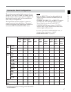
Chapter 1 Overview
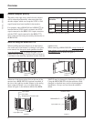
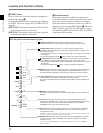
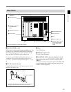
Rear Panel
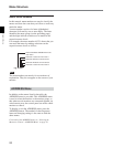
1 MAIN POWER switch
When turned on, the monitor enters standby mode. By
a setting in the SYSTEM CONFIGURATION menu,
the monitor can also be set to enter operation mode
when the MAIN POWER switch is turned on.
For details of the SYSTEM CONFIGURATION menu, see
“Setting the Channel Selection Method and Power-Up
Conditions —SYSTEM CONFIGURATION Menu” on page
42.
2 AC IN connector (3-pin)
Connects the monitor to an AC power source, via the
supplied AC power cord.
(Illustration: BVM-20F1U/20F1E/20E1U/20E1E)
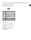
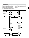
3 Fuse
Use a T4AH fuse.
4 Deflection option slot
Slot for future expansion.
5 CONTROL UNIT connector (female, D-sub 9-
pin)(not provided on BVM-14F5U/14F5E/14E5U/
14E5E)
Connects a monitor control unit such as the BKM-10R
using a straight cable with D-sub 9-pin plugs such as
an RCC-5G (not supplied).
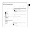
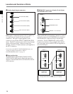
!º ISR connector
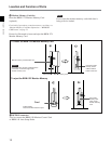
Attach the cord stopper to the AC power cord, and connect it
to the plug holder so that the cord does not come loose.
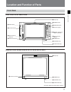
6 Analog input/output
connectors
8 REMOTE 1 connectors
and TERMINATE
switch
9 REMOTE 2 connector
Cord stopper (supplied)
AC power cord (supplied)
Plug holder
7 Input option slots
5 CONTROL UNIT connector
(not provided on BVM-
14F5U/14F5E/14E5U/
14E5E)
1 MAIN POWER switch
2 AC IN connector
4 Deflection option slot
3 Fuse