


17
Chapter 1 Overview
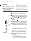
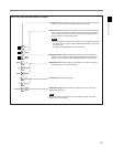
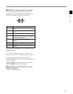
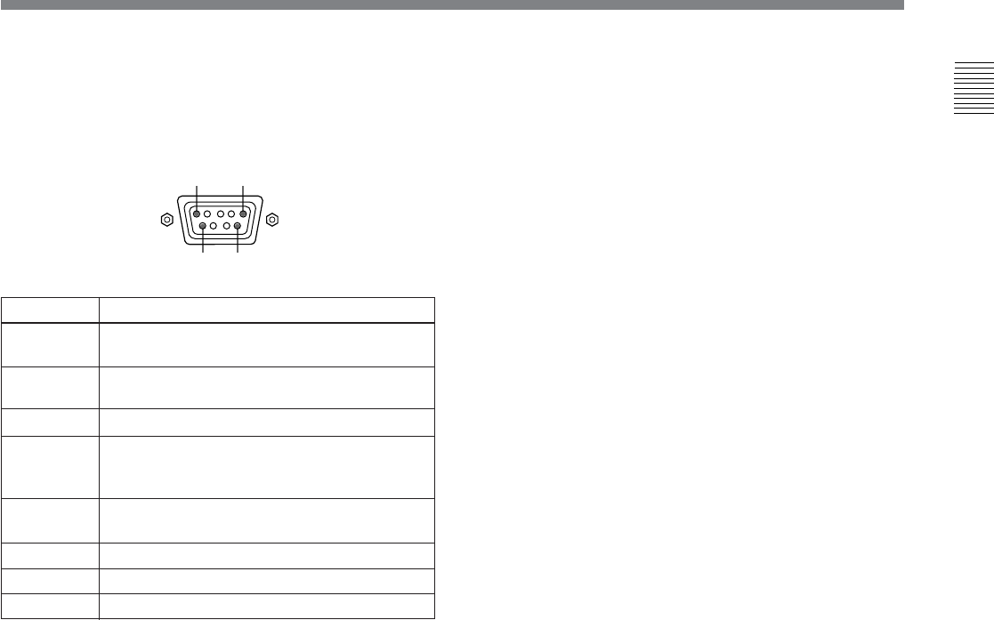
Pin number
1 Set input signal channel 1 (numeric keypad
function)
2 Set input signal channel 2 (numeric keypad
function)
3 Select sync signal (SYNC button function)
4 Set the screen to monochrome, or set for
automatic switching based on the input signal
(MONO button function)
5 Safe area on/off (SAFE AREA button
function)
6, 7 Undefined
8 Tally lamp on/off
9 Ground
All pin function assignments can be changed with the
REMOTE menu.
For details of the REMOTE menu, see “Assigning the
Remote Control Functions —REMOTE Menu” on page 38.
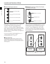
To switch each function between on and off or
between enable and disable, change pin connections in
the following way.
On or enabled: Short each pin and pin 9 together.
Off or disabled: Leave each pin open.
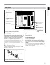
!º ISR (Interactive Status Reporting) connector
(female, D-sub 9-pin)
Connect to the ISR system.
Function
9 REMOTE 2 connector (female, D-sub 9-pin)
Forms a pararell switch and controls the monitor
externally. The pin arrangement and factory setting
function assigned to each pin are given below.
15
96