


16
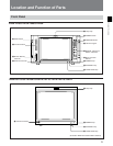
Location and Function of Parts
Chapter 1 Overview
REMOTE 1
IN
TERMINATE
ON
OFF
OUT
REMOTE 1
IN
TERMINATE
ON
OFF
OUT
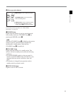
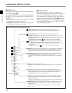
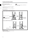
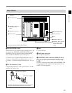
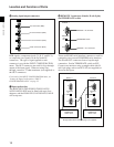
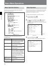
8 REMOTE 1 connectors (female, D-sub 9-pin),
and TERMINATE switch
These are RS-485 serial interface connectors, used for
connecting two or more BVM/HDM-series monitors.
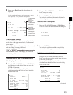
The IN and OUT connectors form a loop-through
connection. Set the TERMINATE switch to OFF.
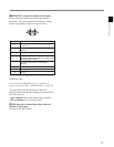
Connect two monitors using a straight cable with D-
sub 9-pin plugs such as an RCC-5G (not supplied) as
shown in the figure.
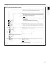
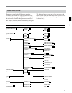
6 Analog input/output connectors
RGB signals, component signals (Y, R–Y, and B–Y),
or composite sync signals can be fed in the IN
connectors. The type of signal applied to each
connector is set with the INPUT CONFIGURATION
menu. The OUT connectors are used for loop-through
output of the input signal. When not using loop-
through, connect a 75-ohm terminator (not supplied) to
the OUT connectors.
For details of the INPUT CONFIGURATION menu, see
“Setting the Input Configuration—INPUT
CONFIGURATION menu” on page 33.
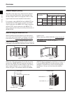
7 Input option slots
The BVM-20F1U/20F1E/20E1U/20E1E/14F5U/
14F5E/14E5U/14E5E may be fitted with up to four
adaptors, and the BVM-14F1U/14F1E/14E1U/14E1E
will accept two.
Y/G connectors (BNC)
B–Y/B connectors (BNC)
IN
Y/G
OUT
IN
OUT
IN
OUT
IN
OUT
B-Y/B
R-Y/R
SYNC
ANALOG
R–Y/R connectors (BNC)
SYNC connectors (BNC)
Monitor 1
Monitor 2
TERMINATE
switch: OFF
TERMINATE
switch: OFF
Straight cable with D-sub 9-pin plugs (not supplied)
REMOTE 1 IN connector
REMOTE 1 OUT connector
TERMINATE switch
REMOTE 1
IN
TERMINATE
ON
OFF
OUT