


1-8
MVS-8000SF
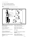
1-4-5. Installing the MKS-8420M
MKS-8420M consists of the following boards.
. CC-90 board : 1 piece
. CPU-DK module :3 pieces
CC-90 board installation
Refer to “1-4-1. Installing the Plug-in Boards”.
CPU-DK module installation
Replace a CPU-DK module on the following boards with
each CPU-DK module of MKS-8420M.
Replacement procedure of the CPU-DK module is de-
scribed as follows using the OUT-23 board as an example.
Other boards (DIF-119, DIF-122, DIF-141, OUT-24,
OUT-27, XPT-21) can also be replaced in the same way.
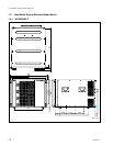
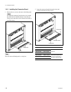
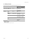
Front side slot No. Board name (The installed boards are
different depending on the system
configuration.)
7 DIF-119 or DIF-122 or DIF-141
(*1)
13 XPT-21
14 OUT-23 or OUT-24 or OUT-27
(*1) : MKS-8170HD, MKS-8170SD, MKS-8170M
Depending on the system configuration, above DME Interface Board
is not installed in slot 7.
c
Be sure to turn off the POWER switch before starting
installation work.
If installation work is started with the POWER switch left
on, it may cause electrical shock or damage to printed
circuit boards.
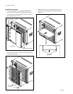
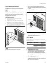
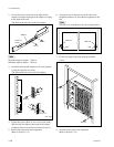
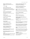
Removal
1. Remove the OUT-23 board from the MVS-8000SF.
2. Remove the two screws and washers. Remove the
bracket (K).
3. Remove the CPU-DK module from the connector of
the board.
4. Peel off the heat conduction sheet 1 (SDI) from the
removed CPU-DK module.
n
The heat conduction sheet 1 (SDI) will be reused.
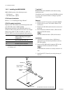
Installation
1. Attach the heat conduction sheet 1 (SDI) that is
removed in step 4 of removal procedure to the new
CPU-DK module.
2. Insert the CPU-DK module connector (PN1) to the
connector (CN1501) on the OUT-23 board.
n
Confirm that the connector is securely inserted to its
root.
3. Install the OUT-23 board by reversing the steps of
removal.
W3,
MIDDLE
CPU-DK
module
Bracket (K)
CN1501
PN1
Heat conduction
sheet 1 (SDI)
B3 x 6
The illustration shows the OUT-23 board.
1-4. Installing the Options