


1-41
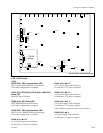
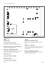
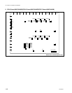
MVS-8000SF
..
..
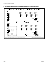
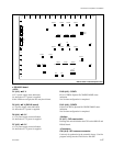
. OUT-23/24 board
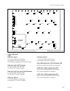
<LED>
D100 (A-3) :
++
++
+12 V
+12 V power supply status indication.
Lit when the +12 V power is supplied.
If this LED does not light, the fuse may have blown.
D104 (A-3) :
++
++
+5 V (OUT-23 board)
+5 V power supply status indication.
Lit when the +5 V power is supplied.
D104 (A-4), D107 (A-3) :
++
++
+5 V (OUT-24 board)
+5 V power supply status indication.
Lit when the +5 V power is supplied.
D105 (A-4) :
++
++
+3.3 V
+3.3 V power supply status indication.
Lit when the +3.3 V power is supplied.
AB C DE F GH J K L MN P R
1
2
3
4
5
6
7
8
9
10
11
12
13
D100
TP101
S100
S1501
D107
TP102
TP103
TP104
D106
E103
E104
E109
E105
TP201
TP205
TP202
TP203
TP600TP700TP900
TP800
TP601
TP1000TP1100TP1200TP1300
TP1001TP1101TP1201TP1301
TP701TP801TP901
TP204
E101
E108
E107
D104
D105
D1400
D1401
CN1400
CN1502
D503
D502
D501
TP502
TP501
TP602
TP1002TP1102TP1202TP1302
TP702TP802TP902
12345
DI1
DI4
SW1
SW2
A
B
C
D
E
F
D8
D7
D6
D3
D2
CPU-DK
Module
*
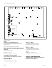
OUT-24 board A side/Component side
D106 (A-4) :
++
++
+2.5 V
+2.5 V power supply status indication.
Lit when the +2.5 V power is supplied.
D501, D502, D503 (A-8) : OUT-CPU status LED
OUT-23 and OUT-24 boards CPU status indication.
D1400 (A-5) : TBC-1 system status LED
TBC-1 system CONFIG DONE status indication.
Not lit when configuration is completed.
D1401 (A-5) : TBC-2 system status LED
TBC-2 system CONFIG DONE status indication.
Not lit when configuration is completed.
1-8. Checks on Completion of Installation
* : The CPU-DK module is installed only in the OUT-24 board of slot 14.