


1-14
MVS-8000SF
1-8. Checks on Completion of Installation
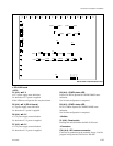
<LED>
D101, D102, D103, D104 (A-4), ND101, ND102 (A-3) :
MAIN CPU status LED
Main CPU status indication.
D309 (A-2) : RESET status LED
System reset status indication.
Lit when S301 is pressed or the power voltage drops to
+3.3 V.
D310 (A-2) : CPU RESET status LED
CA-44 board reset status indication.
Lit when S302 is pressed or the power voltage drops to
+3.3 V.
D501 (A-4), D502, D503, D504 (A-5) : COM CPU-1
status LED
COM CPU-1 status indication.
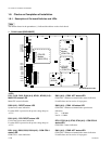
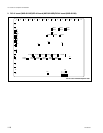
1-8. Checks on Completion of Installation
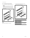
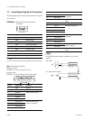
1-8-1. Description of On-board Switches and LEDs
n
The number shown in the parentheses ( ) indicated the address on the circuit board.
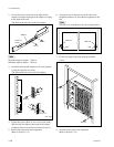
1. CA-44 board (MVS-8000SF)
1
2
3
4
5
AB C D E
D101
D102
D103
D104
TP101
TP102
TP103
TP104
ND101
ND102
ND501
ND502
ND701
ND702
D309
D310
D601
D602
D801
D802
D501
D502
D503
D504
TP501
TP502
TP503
TP504
D701
D702
D703
D704
TP701
TP702
TP703
TP704
D1003
D1002
D1013
D901
D902
D1032
D1033
S101
S501
S701
S102
S103
S104
S502
S702
S302
S301
S303
CN103
CN503
CN703
CN1002
CN1003
E1
E4
E5
E2
E3
TP1031
TP1002
TP1003
TP1001
G
F
E
D
C
B
A
654321
D12
D18
D19
D10
D13
D14
D15
D16
D17
SW2
SW1
F
E
D
C
B
A
12345
DI1
DI4
DI2
DI3
DI6
DI7
DI8
SW1
SW2
F
E
D
C
B
A
12345
DI1
DI4
DI2
DI3
DI6
DI7
DI8
SW1
SW2
S1E1
CPU-DR
Module
(MAIN CPU)
CPU-DK
Module
(COM CPU-1)
CPU-DK
Module
(COM CPU-2)
1
2
3
AB
D1
TP1
TP2
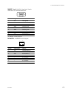
IF-844
(S-BUS)
D100
D101
D200
A
B
12
SG-272
A side/Component side
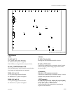
D601 (A-2) : COM1 ACT status LED
COM CPU-1 Ethernet communication status indication.
Lit while data send or receive is in progress.
D602 (A-2) : COM1 100 status LED
COM CPU-1 Ethernet communication speed status
indication.
Lit : 100 Mb/s
Not lit : 10 Mb/s
D701, D702 (A-4), D703, D704 (A-5) : COM CPU-2
status LED
COM CPU-2 status indication.
D801 (A-2) : COM2 ACT status LED
COM CPU-2 Ethernet communication status indication.
Lit while data send or receive is in progress.