


1-12
MVS-8000SF
_ EXT VIEW _
1
5
69
1
13
14
25
EXT VIEW
+V
GPI OUT x B
GPI OUT x A
GPI OUT 5-8
GPI OUT COM
x : 1-4
<Relay>
<Open collector output>
(*3)
(*4)
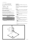
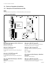
1-7. Input/Output Signals of Connectors
1-7. Input/Output Signals of Connectors
The input/output signals of the connectors at the rear panel
are as follows.
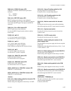
TERMINAL : RS-232C (D-sub 9-pin, Female)
to Terminal
Pin No. Signal Name Function
1 DCD Data Carrier detect
(*1)
2 RXD Received data
3 TXD Transmitted data
4 DTR Data terminal ready
(*1)
5 GND Ground
6 DSR Data set ready
(*1)
7 RTS Request to send
(*2)
8 CTS Clear to send
(*2)
9 __
(*1) :Pins 1, 4 and 6 are internally connected together on the CN-2133
board.
(*2) :Pins 7 and 8 are internally connected together on the CN-2133 board.
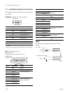
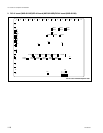
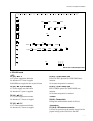
GPI : (D-sub 25-pin, Female)
INPUT x 8, TTL
OUTPUT x 4, relay contacts 30 V 0.1 A
(resistive load)
OUTPUT x 4, open collector, 30 V rated voltage
Pin No. Signal Name Function
1 GND Ground
2 GND Ground
3 GPI IN 2 General-purpose input
4 GPI IN 4
5 GPI IN 6
6 GPI IN 8
7 GPI OUT 1B General-purpose open
8 GPI OUT 2B
collector output (B)
(*3)
9 GPI OUT 3B
10 GPI OUT 4B
Pin No. Signal Name Function
11 GPI OUT 6 General-purpose relay
12 GPI OUT 8
output (B)
(*4)
13 GPI OUT COM Ground for open collector
output
14 GND Ground
15 GPI IN 1 General-purpose input
16 GPI IN 3
17 GPI IN 5
18 GPI IN 7
19 GPI OUT 1A General-purpose relay
20 GPI OUT 2A
output (A)
(*3)
21 GPI OUT 3A
22 GPI OUT 4A
23 GPI OUT 5 General-purpose open
24 GPI OUT 7
collector output
(*4)
25 GPI OUT COM Ground for open collector
output
n
A and B of the same number constitute a pair of relay
contacts.