


1-44
MVS-8000SF
..
..
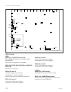
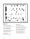
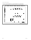
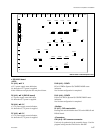
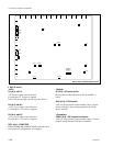
. OUT-27 board
<LED>
D1 (A-3) :
++
++
+12 V
+12 V power supply status indication.
Lit when the +12 V power is supplied.
If this LED does not light, the fuse may have blown.
D700, D701, D702 (A-8) : OUT-CPU status LED
OUT-27 board CPU status indication.
D1600 (A-4) : CONF ERR status LED
FPGA (EP20K100E) CONFIG DONE status indication.
Not lit when all configurations are completed.
D9004 (A-4) :
++
++
+1.8 V
+1.8 V power supply status indication.
Lit when the +1.8 V power is supplied.
D9504 (A-3) :
++
++
+3.3 V
+3.3 V power supply status indication.
Lit when the +3.3 V power is supplied.
ABCDEFGHJKLMNP
S1
D1
S2100
TP1
D9004
TP9501
D1600
E4
TP201
TP205E7
E6
TP202
TP203
TP204
E2
E5
E3
D9504
TP9001
S1600
E1
CN1400
CN1902
D702
D701
D700
TP2100
TP700
TP702
TP701
TP1200TP1300TP1400TP1500
TP800TP900TP1000TP1100
12345
DI1
DI4
SW1
SW2
A
B
C
D
E
F
D8
D7
D6
D3
D2
CPU-DK
Module
*
1
2
3
4
5
6
7
8
9
10
11
12
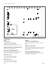
1-8. Checks on Completion of Installation
* : The CPU-DK module is installed only in the OUT-27 board of slot 14. OUT-27 board A side/Component side
<Switch>
S1 (A-3) : OUT-CPU RESET switch
Pressing this switch initializes the CPU on the OUT-27
board.
S1600 (A-5) : JTAG switch
Used only for production in the assembly factory. Set this
switch to ON only when writing program in the JTAG
device with ISP.
S2100 (A-7) : MONITOR reset switch
The reset switch that is used to reset the monitor during
maintenance through the terminal.