


1-50
MVS-8000SF
..
..
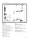
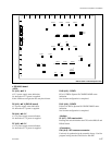
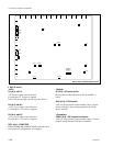
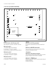
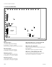
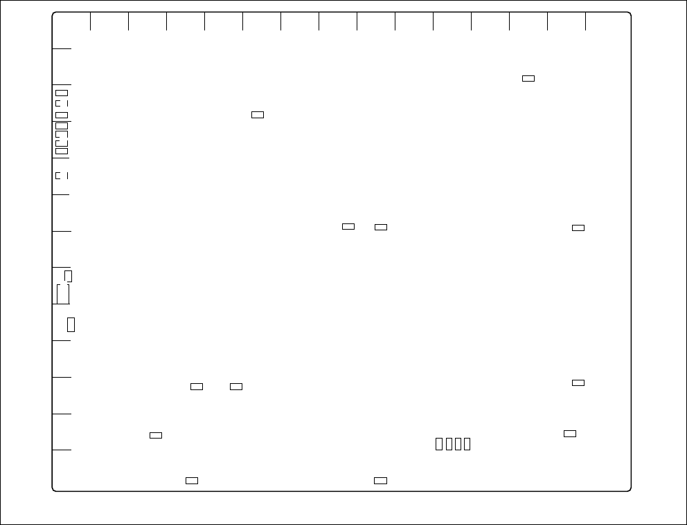
. DIO-74 board
<LED>
D1 (A-3) :
++
++
+12 V
+12 V power supply status indication.
Lit when the +12 V power is supplied.
If this LED does not light, the fuse may have blown.
D2 (A-4) :
++
++
+1.8 V
+1.8 V power supply status indication.
Lit when the +1.8 V power is supplied.
D3 (A-4) :
++
++
+3.3 V
+3.3 V power supply status indication.
Lit when the +3.3 V power is supplied.
D501 (A-4) : CONF ERR
FPGA (EP20K100E) CONFIG DONE status indication.
Not lit when all configurations are completed.
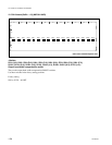
CN601
AB C DE F GH J K L MN P R
1
2
3
4
5
6
7
8
9
10
11
12
13
D501
D1
D2
TP9001
TP9501
TP1
E6
D3
S601
S1
TP102
TP103TP104
E7
TP201
TP202
TP203
TP204
E5
E4
E1
E2
E3
TP101
TP1001
TP1501
DIO-74 board A side/Component side
<Switch>
S1 (A-9) : DIO reset switch
Pressing this switch initializes the CPU on the DIO-74
board.
S601 (A-8) : JTAG switch
Used only for production in the assembly factory. Set this
switch to ON only when writing program in the JTAG
device with ISP.
<Connector>
CN601 (A-8) : ISP common connector
Used only for production in the assembly factory. Used for
program writing into the JTAG device with ISP.
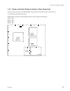
1-8. Checks on Completion of Installation