


1-38
MVS-8000SF
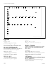
1-8. Checks on Completion of Installation
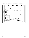
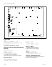
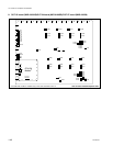
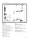
7. XPT-21 board (MVS-8000SF)
E9
E7
AB C DE F GH J K L MN P R
1
2
3
4
5
6
7
8
9
10
11
12
13
D3401
S3401
CN3001
CN3301
E3
TP3001E4
TP3005
TP3002
TP3004
TP3003
E1
E2
E8
TP1
TP2
E10
D2
D3
D4
CN3303
S3301
CN3901
E6
TP3401
E5
12345
DI1
DI4
SW1
SW2
A
B
C
D
E
F
D8
D7
D6
D3
D2
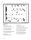
CPU-DK
Module
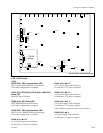
A side/Component side
<LED>
D3401 (A-5) : RESET status LED
System reset status indication.
Lit when S3401 is pressed or the power voltage drops to
+3.3 V.
D3 (A-5) :
++
++
+3.3 V
+3.3 V power supply status indication.
Lit when the +3.3 V power is supplied.
D4 (A-6) :
++
++
+2.5 V
+2.5 V power supply status indication.
Lit when the + 2.5 V power is supplied.
D2 (A-5) :
++
++
+12 V
+12 V power supply status indication.
Lit when the +12 V power is supplied.
<Switch>
S3401 (A-8) : XPT-RESET switch
Pressing this switch initializes the CPU on the XPT-21
board.
S3301 (A-10) : MONITOR switch
Factory use only. (Do not change the setting.)
<Connector>
CN3001 (A-8) : ISP common connector
Used only for production in the assembly factory. Used for
program writing into the JTAG device with ISP.
CN3301 (A-4) : TERMINAL pin
This pin is connected to the CPU control terminal and used
during maintenance.
Conforms to RS-232C.