


1-17
MVS-8000SF
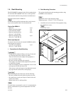
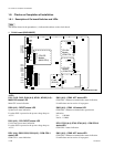
1-8. Checks on Completion of Installation
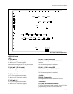
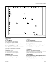
DI3 (F-3), DI6 (F-3), DI7 (F-3), DI8 (F-4) (green) :
STATUS1 to STATUS4 LED
Used for maintenance purpose. Only the STATUS1 LED is
lit in normal operation.
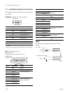
DI4 (green) (B-5) :
++
++
+3.3 V
Indicates the status of the VCC (CORE) and VCC (I/O)
powers that are supplied to the CPU-DK module.
<Switch on the CPU DK module> : COM CPU-1
: COM CPU-2
SW1 (D-5) : RESET switch
Pressing this switch resets the CPU-DK module.
n
In some machines in which the CPU-DK module is
installed, the system reset may be activated.
SW2 (C-5) : MODE switch
8-pin DIP switch
Used only for production in the assembly factory. All
switches are set to OFF for normal operation.
Default setting when shipped from the factory is all OFF.
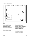
<LED on the IF-844 board> : S-BUS
D1 (B-1) : SBUS RX status LED
Lit when receiving data.
<Switch on the IF-844 board> : S-BUS
S1 (B-3) : RESET switch
Pressing this switch resets the IF-844 board.
<TEST terminal on the IF-844 board>
E1 (B-3) : GND terminal
Use this terminal as the earth point for measuring the
respective check terminals.
TP1 (A-2) : RX check terminal
S-BUS communication line measuring terminal.
TP2 (A-3) : TEST terminal
Terminal for testing.
<LED on the SG-272 board>
D100 (B-1) : REF OK status LED
Lit while V sync of the reference input is detected.
D101 (B-1) : REF EXT status LED
Lit while sync signal is input to the reference input.
D200 (B-1) : LOCK status LED
Lit while the machine is locked to the reference signal.