


1-19
MVS-8000SF
1-8. Checks on Completion of Installation
..
..
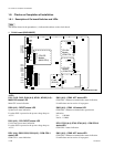
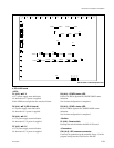
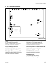
. DO-41/42 board
<LED>
D1 (A-3) :
++
++
+12 V
+12 V power supply status indication.
Lit when the +12 V power is supplied.
If this LED does not light, the fuse may have blown.
D5 (A-4) :
++
++
+5 V (DO-41 board)
+5 V power supply status indication.
Lit when the +5 V power is supplied.
D6 (A-4) :
++
++
+3.3 V
+3.3 V power supply status indication.
Lit when the +3.3 V power is supplied.
D7 (A-5) :
++
++
+2.5 V
+2.5 V power supply status indication.
Lit when the +2.5 V power is supplied.
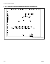
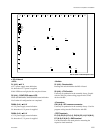
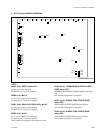
DO-42 board A side/Component side
AB C DE F GH J K L MN P R
1
2
3
4
5
6
7
8
9
10
11
12
13
D1
TP2
D6
TP1
D7
TP3
D9
D8
CN1
S1
E1
E2
E3
E4
E5
TP6
TP7
TP8
TP9
E7
TP4
TP5
TP1000
TP1500 TP2000 TP2500 TP3000 TP3500
TP4000
TP4500TP6000
TP1001
TP1002
TP1501
TP1502
TP2001
TP2002
TP2501
TP2502
TP3001
TP3002
TP3501
TP3502
TP4001
TP6001
TP4002
TP6002
E6
D8 (A-6) : CONF2 status LED
D10 to L10 FPGA (Spartan II) CONFIG DONE status
indication.
Not lit when configuration is completed.
D9 (A-5) : CONF1 status LED
H2 to L2 FPGA (Spartan II) CONFIG DONE status
indication.
Not lit when configuration is completed.
<Switch>
S1 (A-8) : Reset switch
Pressing this switch initializes the DO-41/42 board.
<Connector>
CN1 (A-6) : ISP common connector
Used only for production in the assembly factory. Used for
program writing into the JTAG device with ISP.