


1-15
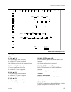
MVS-8000SF
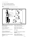
D802 (A-2) : COM2 100 status LED
COM CPU-2 Ethernet communication speed status
indication.
Lit : 100 Mb/s
Not lit : 10 Mb/s
D901 (A-2) : REF EXT status LED
REF IN signal presence/absence status indication.
Lit when the REF signal is input to the REF IN connector.
Not lit when the REF signal is not input to the REF IN
connector.
D902 (A-2) : PLL LOCK status LED
REF IN signal format status indication.
Lit when the REF IN signal matches with the switcher
format setup.
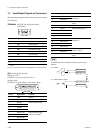
D1002 (A-2) :
++
++
+3.3 V
+3.3 V power supply status indication.
Lit when the +3.3 V power is supplied.
D1003 (A-1) :
++
++
+12 V
+12 V power supply status indication.
Lit when the +12 V power is supplied.
If this LED does not light, the fuse may have blown.
D1013 (A-2) :
++
++
+5 V
+5 V power supply status indication.
Lit when the +5 V power is supplied.
D1032 (A-2) : SBUS TX status LED
S-BUS send status indication.
Lit while the data send is in progress.
D1033 (A-2) : SBUS RX status LED
S-BUS receive status indication.
Lit while the data receive is in progress.
ND501, ND502 (A-4) : COM CPU-1 status LED
COM CPU-1 status indication.
ND701, ND702 (A-4) : COM CPU-2 status LED
COM CPU-2 status indication.
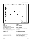
<Switch>
S101 (A-3) : Mode setting switch for the main CPU
Sets the modes of the main CPU.
Default setting when shipped from the factory is all OFF.
S102 (A-2) : Group ID setting switch for LAN
Sets the group ID for connecting LAN.
For details, refer to “System Setup Manual”.
S103 (A-2) : Unit ID setting switch for LAN
Sets the unit ID for connecting LAN.
For details, refer to “System Setup Manual”.
S104 (A-4) : Monitor reset switch for the main
CPU
Pressing this switch resets the system while maintaining
this unit through the main CPU control terminal connector.
S301 (A-1) : System reset switch
Pressing this switch activates the system reset and the
system re-starts.
S302 (A-1) : CA-CPU reset switch
Pressing this switch resets the CA-44 board.
S303 (B-1) : Switch setting the number of the
power supply units
Sets the number of the power supply units that are required
for this unit.
Default setup when shipped from the factory is bits 1, 2 and
4 :
OFF, and bits 3 : ON.
S501 (A-4) : Modes setting switch for the COM CPU-1
Sets the modes of the COM CPU-1.
Default setting when shipped from the factory is all OFF.
S502 (A-4) : Monitor reset switch for the COM CPU-1
Pressing this switch resets the system while maintaining
this unit through the COM CPU-1 control terminal.
S701 (A-4) : Modes setting switch for the COM
CPU-2
Default setting when shipped from the factory is all OFF.
S702 (A-4) : Monitor reset switch for the COM CPU-2
Pressing this switch resets the system while maintaining
this unit through the COM CPU-2 control terminal.
<Connector>
CN103 (A-4) : TERMINAL pin
This pin is connected to the main CPU control terminal
and used during maintenance.
Conforms to RS-232C.
1-8. Checks on Completion of Installation