Chapter 3 Setup and Power-On Procedures 37
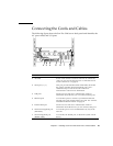
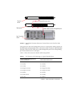
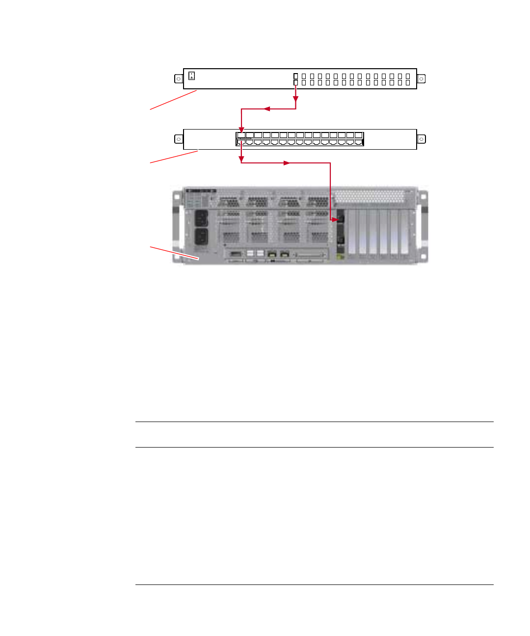
FIGURE 3-1 Patch Panel Connection Between a Terminal Server and a Sun Fire V440
Server
If the pinouts for the serial management port do not correspond with the pinouts for
the RJ-45 ports on the terminal server, you need to make a crossover cable that takes
each pin on the Sun Fire V440 server serial management port to the corresponding
pin in the terminal server’s serial port.
TABLE 3-1 shows the crossovers that the cable must perform.
TABLE 3-1 Pin Crossovers for Connecting to a Typical Terminal Server
Sun Fire V440 Serial Management Port
(RJ-45 Connector) Pin Terminal Server Serial Port Pin
Pin 1 (RTS) Pin 1 (CTS)
Pin 2 (DTR) Pin 2 (DSR)
Pin 3 (TXD) Pin 3 (RXD)
Pin 4 (Signal Ground) Pin 4 (Signal Ground)
Pin 5 (Signal Ground) Pin 5 (Signal Ground)
Pin 6 (RXD) Pin 6 (TXD)
Pin 7 (DSR /DCD) Pin 7 (DTR)
Pin 8 (CTS) Pin 8 (RTS)
12
3
4
56
7
8
91011
12 13
14
15
1
2
3
4
5
6
7
8
9
10
11
12
13
14
15
Terminal
server
Patch panel
Sun Fire V440
server
Straight-through cable
Patch cable to serial management port


