Chapter 3 Setup and Power-On Procedures 45
2. Turn on power to any peripherals and external storage devices.
Read the documentation supplied with the device for specific instructions.
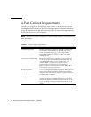
3. Connect the Sun Fire V440 server’s outlet plug of each power cord to the power
sequencer in the cabinet (if your type of cabinet includes one), to a grounded
outlet strip, or to a grounded AC power outlet.
Note – Each outlet must connect the server to a 15A circuit for North America and
Japan, and to a 10A or 16A circuit for Europe. Consult your local electrical codes for
any additional requirements. See the instructions provided with your cabinet for
information about the power sequencer.
Note – Connect each cord to a separate circuit to maximize system availability.
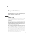
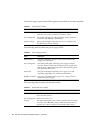
The Standby LEDs on the power supplies are lit, indicating that power is being
supplied. As soon as you plug in the power cord, several boot messages from the
ALOM software are displayed on your system console device. The ALOM boot
messages end with the ALOM sc> prompt.
4. Unlock and open the right system door, as viewed from the front of the system.
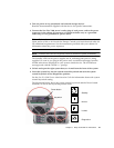
5. Insert the system key into the system control keyswitch and turn the system
control keyswitch to the Diagnostics position.
See the Sun Fire V440 Server Administration Guide for information about each system
control keyswitch setting.
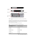
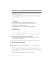
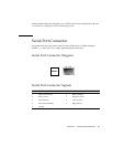
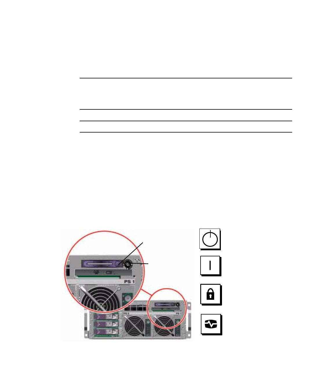
The illustration below shows the system control keyswitch and the Power button
locations, as well as the keyswitch position icons.
Keyswitch
Power button
Standby
Normal
Locked
Diagnostics


