


Appendix A Field-Replaceable Units (FRUs) 77
1
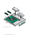
TABLE A-1 Sun Fire T1000 Server FRU List
Item No. CRU
Replacement
Instructions Description Location
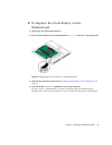
1 Motherboard
and chassis
assembly
“To Remove the
Motherboard and
Chassis” on
page 68
The motherboard and chassis are
replaced as a single assembly. The
motherboard is provided in different
configurations to accommodate the
different processor models (6 core and
8 core).
MB
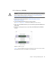
2 DIMMs “To Remove
DIMMs” on
page 65
Can be ordered in the following sizes:
• 512 MB
•1GB
•2GB
See
TABLE A-2
and
FIGURE 3-11.
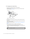
3 Fan assembly “To Remove the
Fan Tray
Assembly” on
page 60
A single assembly containing 4 fans. FAN_TRAY
4 Power supply
unit (PS)
“To Remove the
Power Supply” on
page 61
The power supply provides -3.3 Vdc
standby power at 3 @ 3 Amps and 12
Vdc at 25 Amps.
PS0
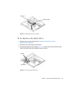
5 Hard drive “To Remove the
Hard Drive” on
page 63
SATA disk drive, 3.5-inch form factor HD0
6 PCI Express
card slot
“To Remove the
Optional PCI
Express Card” on
page 58
Optional add-on express card PCI0
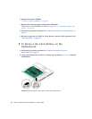
7 Clock battery “To Remove the
Clock Battery on
the Motherboard”
on page 70
Battery is located on the motherboard. SC/BAT
8 SEEPROM Remove and
replace the
socketed
SEEPROM.
The socketed SEEPROM contains the
MAC address and system
configuration information.
MB/SEEPROM