


Chapter 5: Advanced Serverboard Setup
5-9
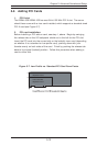
5-3 Connecting Cables
Now that the processors are installed, the next step is to connect the cables to
the serverboard. These include the data (ribbon) cables for the peripherals and
control panel and the power cables.
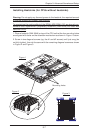
Connecting Data Cables
The ribbon cables used to transfer data from the peripheral devices have been
carefully routed in preconfigured systems to prevent them from blocking the flow
of cooling air that moves through the system from front to back. If you need to
disconnect any of these cables, you should take care to keep them routed as
they were originally after reconnecting them (make sure the red wires connect to
the pin 1 locations). If you are configuring the system, keep the airflow in mind
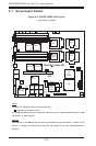
when routing the cables. The following data cables (with their serverboard con-
nector locations noted) should be connected. See the serverboard layout figure
in this chapter for connector locations.
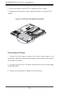
! SCSI Device Cable (J3, 6113L-8 only)
! IDE Device Cable (J37, 6113L-i only)
! CD-ROM Cable (J35)
! Front Side COM Port Cable (J38)
! Front Side USB Cable (J21)
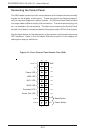
! Control Panel Cable (U66, see next page)
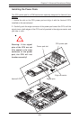
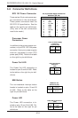
Connecting Power Cables
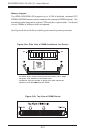
The i2DML-8G2/i2DML-iG2 has two 24-pin primary power supply connectors
designated J20 and J36 for connection to the ATX power supply. Connect the
appropriate connector from the power supply to the either of these two connec-
tors (only one connection is required) to supply power to the serverboard. See
the Connector Definitions section in this chapter for J20 and J36 pin definitions.
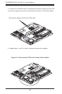
In addition, each processor requires a power pod. Each power pod must have
power supplied to it via one of the 4-pin header connectors included with your
power supply.