


Chapter 5: Advanced Serverboard Setup
5-11
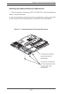
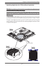
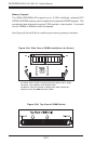
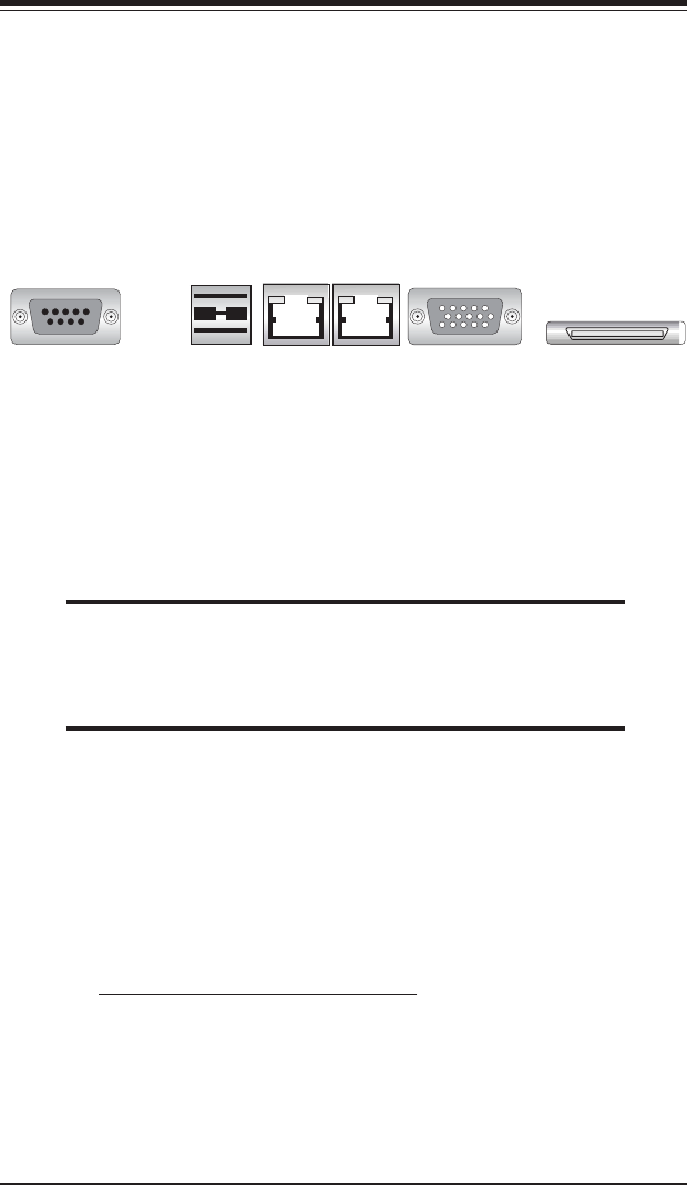
5-4 I/O Ports
The I/O ports are color coded in conformance with the PC 99 specification. See
Figure 5-5 below for the locations of the various I/O ports.
Figure 5-5. I/O Port Locations
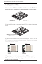
5-5 Installing Memory
Note: Check the Supermicro web site for recommended memory modules: http://
www.supermicro.com/support/
CAUTION
Exercise extreme care when installing or removing DIMM modules
to prevent any possible damage. Also note that the memory is
interleaved to improve performance (see step 1).
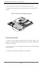
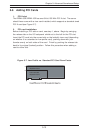
DIMM Installation (See Figure 5-6)
1. Insert four identical DIMMs (modules of the same size and type) into the
DIMM1, DIMM2, DIMM3 and DIMM4 sockets (J16, J13, J11 and J9,
repectively). (These four DIMM sockets are colored blue.) If eight DIMMs
are to be used, insert four more identical DIMMs into the DIMM5, DIMM6,
DIMM7 and DIMM8 sockets (J15, J14, J12, and J10, respectively). (These
four DIMM sockets are colored black.) The memory scheme is interleaved,
so you must install four modules at a time, beginning with the blue DIMM1,
DIMM2, DIMM3 and DIMM4 sockets.
2. Insert each DIMM module vertically into its socket. Pay attention to the notch
along the bottom of the module to prevent inserting the DIMM module incor-
rectly.
3. Gently press down on the DIMM module until it snaps into place in the socket.
Repeat for all modules (see step 1 above).
COM Port USB Ports GLAN1 GLAN2 VGA Port External SCSI
(6113L-8 only)