


SUPERSERVER 6113L-8/6113L-i User's Manual
5-22
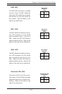
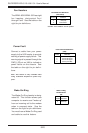
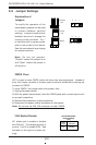
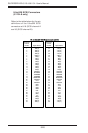
VGA Enable/Disable
JV1 allows you to enable or disable
the VGA port. The default position is
on pins 1 and 2 to enable VGA. See
the table on the right for jumper set-
tings.
Jumper
Position
1-2
2-3
Definition
Enabled
Disabled
VGA Enable/Disable
Jumper Settings
(JV1)
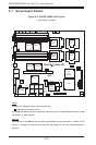
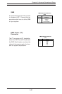
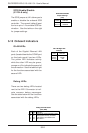
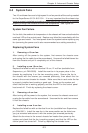
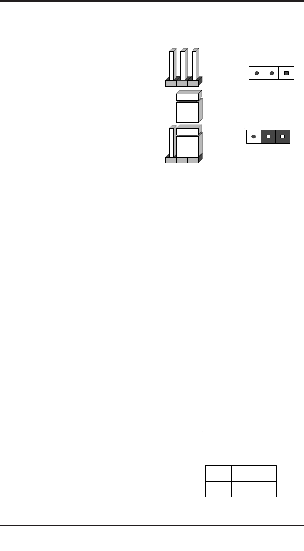
5-9 Jumper Settings
Explanation of
Jumpers
To modify the operation of the
serverboard, jumpers can be used
to choose between optional
settings. Jumpers create shorts
between two pins to change the
function of the connector. Pin 1
is identified with a square solder
pad on the printed circuit board.
See the serverboard layout page
for jumper locations.
Note: On two pin jumpers,
"Closed" means the jumper is on
and "Open" means the jumper is
off the pins.
Connector
Pins
Jumper
Cap
Setting
Pin 1-2 short
3 2 1
3 2 1
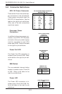
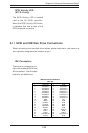
CMOS Clear
JBT1 is used to clear CMOS (which will also clear any passwords). Instead of
pins, this jumper consists of contact pads to prevent accidentally clearing the
contents of CMOS.
To clear CMOS, first power down the system, then
1) Unplug the power cord(s)
2) With the power disconnected, short the CMOS pads with a metal object such
as a small screwdriver
3) Remove the screwdriver (or shorting device)
4) Reconnect the power cord(s) and power on the system.
Note: Do not use the PW_ON connector to clear CMOS.