


SUPERSERVER 6113L-8/6113L-i User's Manual
5-10
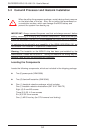
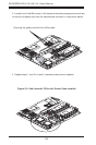
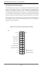
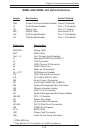
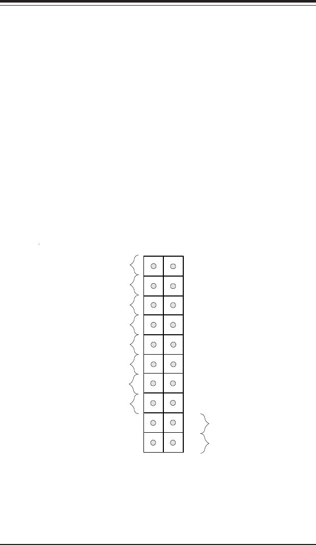
Figure 5-4. Front Control Panel Header Pins (U66)
Power Button
Overheat LED
1
NIC1 LED
Reset Button
2
Power Fail LED
NIC2 LED
HDD LED
Power LED
Reset
Pwr
Vcc
Vcc
Vcc
Vcc
Vcc
Ground
Ground
1920
Vcc
X
Ground
NMI
X
Connecting the Control Panel
The U66 header contains pins for various buttons and indicators that are normally
located on the chassis control panel. These connectors are designed specifi-
cally for use with Supermicro server chassis. All U66 wires have been bundled
into single ribbon cable to simplify their connection. The red wire should plug into
pin 1 as marked on the serverboard. The other end connects to the Control Panel
printed circuit board, located just behind the system status LEDs in the chassis.
See the figure below for the descriptions of the various control panel buttons and
LED indicators. Refer to the Connector Definitions section in this chapter for
descriptions and pin definitions.