


Chapter 5: Advanced Serverboard Setup
5-25
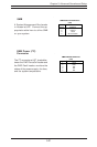
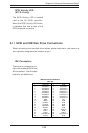
5-11 SCSI and IDE Disk Drive Connections
When connecting the hard disk drive cables, please note that a red mark on a
wire typically designates the location of pin 1.
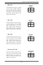
SCSI Activity LED
(6113L-8 only)
The SCSI Activity LED is located
next to the LSI SCSI controller.
When the SCSI Activity LED blinks,
it indicates that one or both of the
SCSI channels are active.
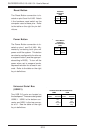
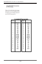
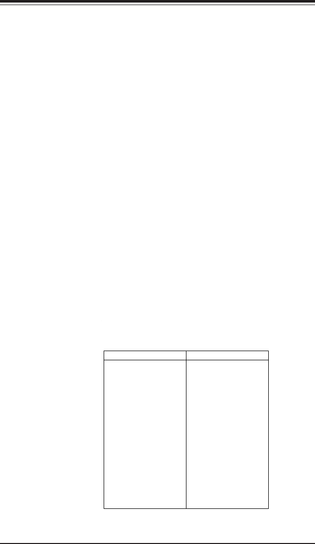
IDE Connectors
There are no jumpers to con-
figure the onboard IDE#1 and
#2 connectors. See the table
below for pin definitions.
Pin Number Function
1 Reset IDE
3 Host Data 7
5 Host Data 6
7 Host Data 5
9 Host Data 4
11 Host Data 3
13 Host Data 2
15 Host Data 1
17 Host Data 0
19 GND
21 DRQ3
23 I/O Write-
25 I/O Read-
27 IOCHRDY
29 DACK3-
31 IRQ14
33 Addr 1
35 Addr 0
37 Chip Select 0
39 Activity
Pin Number Function
2 GND
4 Host Data 8
6 Host Data 9
8 Host Data 10
10 Host Data 11
12 Host Data 12
14 Host Data 13
16 Host Data 14
18 Host Data 15
20 Key
22 GND
24 GND
26 GND
28 BALE
30 GND
32 IOCS16-
34 GND
36 Addr 2
38 Chip Select 1-
40 GND
IDE Connector Pin Definitions
(J37, J35)