


SUPERSERVER 6113L-8/6113L-i User's Manual
5-16
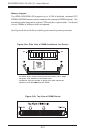
5-8 Connector Definitions
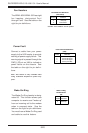
Pins
1 thru 2
3 thru 4
Definition
Ground
+12v
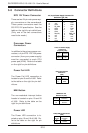
4-Pin, 12v Power Supply
Connectors
(to power pods)
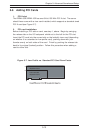
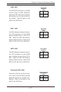
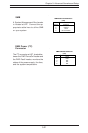
EPS 12V Power Connector
There are two 24-pin main power sup-
ply connectors on the serverboard.
These power connectors meet the
SSI EPS 12V specification. See the
table on the right for pin definitions.
(Only one of the two connections
need to be made.)
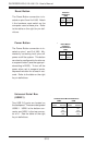
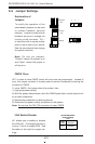
Power Fail LED
The Power Fail LED connection is
located on pins 5 and 6 of U66. Refer
to the table on the right for pin defi-
nitions.
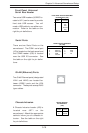
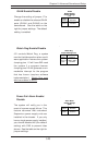
Power LED
The Power LED connection is lo-
cated on pins 15 and 16 of U66. Re-
fer to the table on the right for pin
definitions.
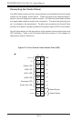
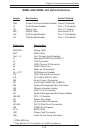
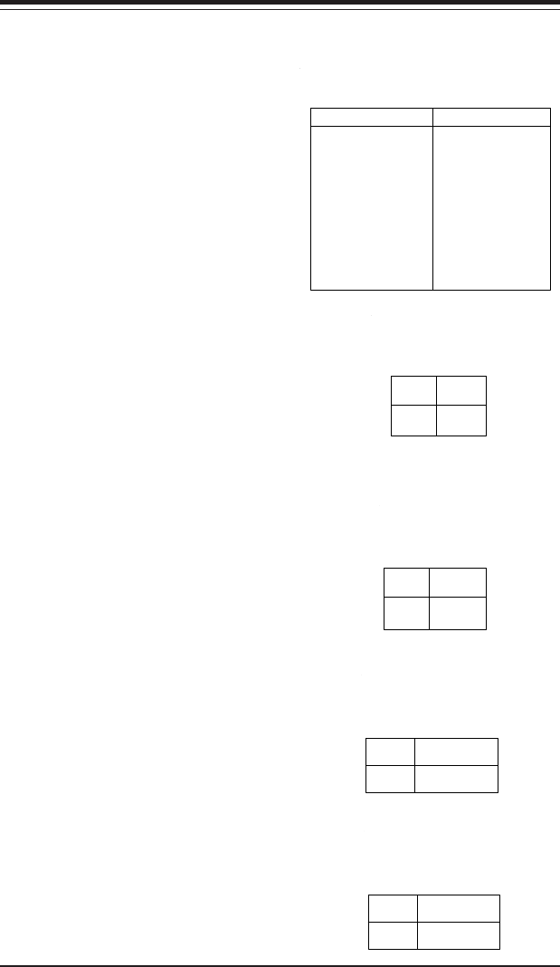
12V, 24-pin Power Supply Connector Pin
Definitions (J20, J36)
Pin Number Definition
13 +3.3V
14 -12V
15 COM
16 PS_ON#
17 COM
18 COM
19 COM
20 Res(NC)
21 +5V
22 +5V
23 +5V
24 COM
Pin Number Definition
1 +3.3V
2 +3.3V
3 COM
4 +5V
5 COM
6 +5V
7 COM
8 PWR_OK
9 5VSB
10 +12V
11 +12V
12 +3.3V
NMI Button
The non-maskable interrupt button
header is located on pins 19 and 20
of U66. Refer to the table on the
right for pin definitions.
Pin
Number
19
20
Definition
Control
Ground
NMI Button Pin
Definitions (U66)
Pin
Number
15
16
Definition
Vcc
Control
PWR_LED Pin Definitions
(U66)
Power Fail LED Pin
Definitions
(U66)
Pin
Number
5
6
Definition
Vcc
GND
Processor Power
Connectors
In addition to the primary power con-
nectors, a 4-pin EPS 12V/15A power
connector (from your power supply)
must be connected to each CPU
power pod (VRM). Refer to the table
on the right for pin definitions.