


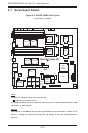
Chapter 5: Advanced Serverboard Setup
5-19
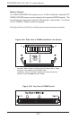
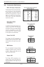
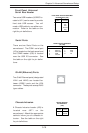
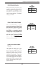
Front Panel Universal
Serial Bus Header
Two extra USB headers (USB2/3 lo-
cated at J21) can be used to provide
front side USB access. You will
need a USB cable to use either con-
nection. Refer to the table on the
right for pin definitions.
Front Panel Universal Serial Bus
Pin Definitions (J21)
Pin
Number Definition
1+5V
2P0-
3P0+
4 Ground
5Key
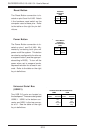
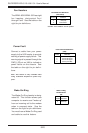
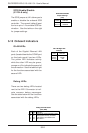
Chassis Intrusion
A Chassis Intrusion header (J25) is
located near JBT1 on the
serverboard. Attach the appropriate
cable to inform you of a chassis in-
trusion. See the table on the right
for pin definitions.
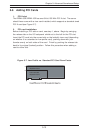
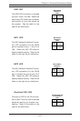
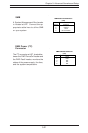
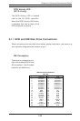
Serial Ports
There are two Serial Ports on the
serverboard. The COM1 serial port
(J5) is located on the back panel and
the COM2 header (J38) is located
near the USB 2/3 connector. See
the table on the right for pin defini-
tions.
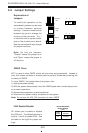
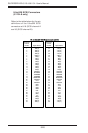
GLAN (Ethernet) Ports
Two G-bit Ethernet ports (designated
LAN1 and LAN2) are located be-
tween USB0/1 ports and the VGA
connector. These ports accept RJ45
type cables.
Serial Ports Pin Definitions
(J5, J38)
Pin Number Definition
1 DCD
2 Serial In
3 Serial Out
4 DTR
5 Ground
Pin Number Definition
6 DSR
7 RTS
8 CTS
9 RI
Pin
Number
1
2
Definition
Instrusion
Ground
Chassis Intrusion
Pin Definitions
(J25)