


6-2
SUPERSERVER 6113L-8/6113L-i User's Manual
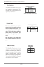
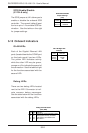
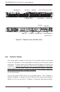
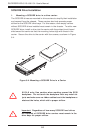
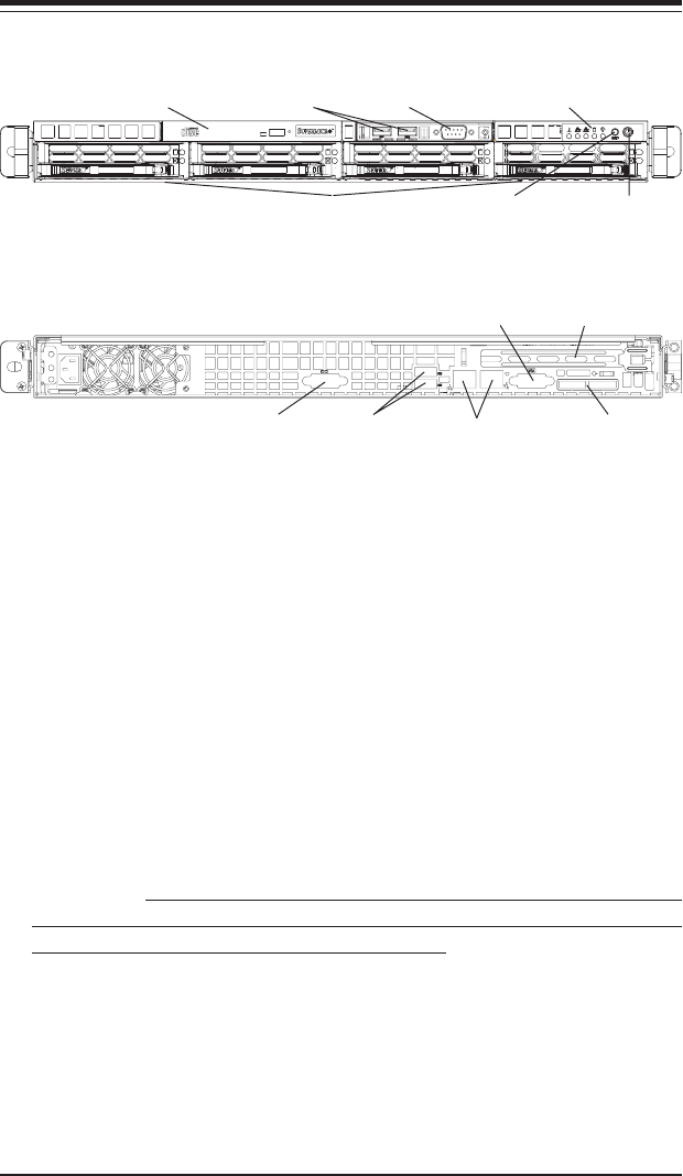
Figure 6-1. Chassis: Front and Rear Views
6-2 Control Panel
The control panel (located on the front of the chassis) must be connected
to the JF2 connector on the serverboard to provide you with system status
indications. A ribbon cable has bundled these wires together to simplify the
connection. Connect the cable from JF2 on the serverboard to the appro-
priate header on the Control Panel PCB (printed circuit board). Make sure
the red wire plugs into pin 1 on both connectors. Pull all excess cabling out
of the airflow path.
The control panel LEDs inform you of system status. See "Chapter 3:
System Interface" for details on the LEDs and the control panel buttons.
Details on JF2 can be found in "Chapter 5: Advanced Serverboard Setup."
CD-ROM Drive USB Ports
System Reset
Control Panel/System LEDs
Main PowerSCSI/IDE Drives
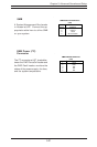
Ethernet PortsCOM1 Port
VGA Port
USB Ports
PCI-X Slot
COM Port
External SCSI Port
(6113L-8 only)