


SUPERSERVER 6113L-8/6113L-i User's Manual
5-20
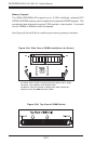
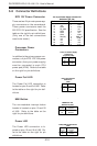
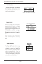
Power Fault
Connect a cable from your power
supply to the U62 header to provide
warning of power supply failure. This
warning signal is passed through the
PWR_LED pin on U66 to indicate a
power failure on the chassis. See
the table on the right for pin defini-
tions.
Note: This feature is only available when
using redundant Supermicro power sup-
plies.
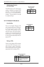
Power Fault Pin Definitions
(U62)
Pin
Number
1
2
3
4
Definition
P/S 1 Fail Signal
P/S 2 Fail Signal
P/S 3 Fail Signal
Reset (from MB)
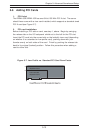
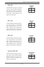
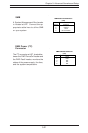
Wake-On-Ring
The Wake-On-Ring header is desig-
nated J6. This function allows your
computer to receive and "wake-up"
from an incoming call to the modem
when in suspend state. See the
table on the right for pin definitions.
You must have a Wake-On-Ring card
and cable to use this feature.
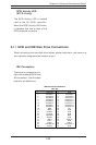
Wake-on-Ring
Pin Definitions
(J6)
Pin
Number
1
2
Definition
Ground
Wake-up
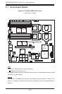
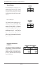
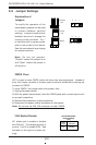
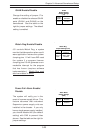
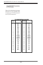
Fan Header Pin Definitions
(Fan1-Fan8)
Pin
Number
1
2
3
Definition
Ground (black)
+12V (red)
Tachometer
Fan Headers
The i2DML-8G2/i2DML-iG2 has eight
fan headers, designated Fan1
through Fan8. See the table on the
right for pin definitions.
Caution: Fan headers are DC power.