


2-3
Chapter 2: Connectors, Jumpers and Indicators
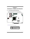
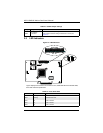
2-2 Front Jumper Locations and Pin Definitions
To modify the operation of the backplane, jumpers can be used to choose between
optional settings. Jumpers create shorts between two pins to change the function of the
connector. Pin 1 is identified with a square solder pad on the printed circuit board.
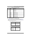
Figure 2-2 shows jumper locations for the add-on card, while Table 2-3 lists the add-on
card’s pin definitions.
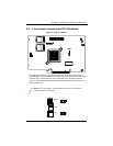
Figure 2-2. Jumper Locations
NOTE: On two pin jumpers, "Closed" means the jumper is on and "Open"
means the jumper is off the pins.
SWR5
Connector
Pins
Jumper
Setting
3 2 1
3 2 1