


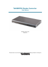

TANDBERG Border Controller User Manual
1.1 TANDBERG Border Controller Overview
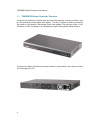
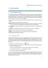
On the front of the Border Controller there are three LAN interfaces, a serial port (Data 1) and
an LED showing the power status of the system. The LAN 1 interface is used for connecting
the system to your network, LAN interface 2 and 3 are disabled. The serial port (Data 1) is for
connection to a PC, and power on is indicated by the Light Emitting Diode (Power) being lit.
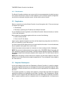
The back of the Border Controller has a power connector, a power switch, and a serial port (Data
2) for connecting to a PC.
2