Theory of Operation 4-23
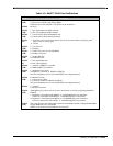
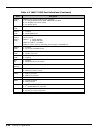
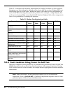
Table 4-5 M6377 GPIO Port Definitions
Item Description
GPIO17
(W/R)
1: Connect serial BUS with charger ROM.
0: Disconnect serial BUS with charger ROM.
GPIO20 is the CLK and GPIO21 is the DATA for the serial BUS.
GPIO16 Reserved
GPIO15
(W/R)
1: CPU high temperature SMI is allowed.
0: CPU low temperature SMI is allowed.
GPIO14
(W/R)
1: Connect the ZV BUS with PCMCIA card.
0: Connect the ZV BUS with Feature board.
GPIO13
(W)
1: Force the system to enter 0V suspend or power down mode, and then could press power
button to turn on system again.
0: Normal
GPIO12
(W/R)
1: Force FAN on
0: Normally
GPIO11
(W/R)
1: Enable+12V power foor FLASH ROM.
0: Disable+12V power.
GPIO10
(W/R)
1: Disable FIR VCC.
0: Enable FIR VCC.
GPIO27
(R)
1: CPU high temperature.
0: CPU low temperature.
GPIO26
(W/R)
1: notebook’s SMBUS is accessible.
0: MPB’s SMBUS is accessible.
GPIO25
(W/R)
1: Brightness level is fixed
0: Brightness is trimable via GPIO22 & GPIO20.
The current brightness level is stored when PIO25 low to high transations.
GPIO24
(W/R)
For DSTN LCD only.
1: Contrast level is fixed.
0: Contrast is trimable via GPIO22 & GPIO20.
The current brightness level is stored when PIO25 low to high transations.
GPIO23 1: Normally
0: Ready to transations.
GPIO22
(W/R)
The Brightness & Contrast for LCD system is devided into 32 scale by programing GPIO22 &
GPIO20.
1: Brightness is incremented with GPIO23 “L” and GPIO20 high to low transations.
Contrast is incremented with GPIO24 :L” and GPIO20 high to low transations.
0: Brightness is decremented with GPIO24 “L” and GPIO20 high to low transations.
Contrast is decremented with GPIO23 “L” and GPIO20 high to low transations.
GPIO21
(W/R)
The system provide a serial BUS while wired to Inverter ROM, notebook’s Charger ROM, MPB’s
Charger ROM and Uma’s dock ROM.
GPIO21 is the serial DAT and GPIO20 is the serial CLK.


