


4-24 Theory of Operation
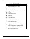
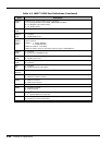
Table 4-5 M6377 GPIO Port Definitions (Continued)
Item Description
GPIO20
(W/R)
GPIO20 is the common CLK for below serial BUS:
A. For Charger ROM, Inverter ROM, MPB ROM serial BUS.
B. For Brightness & Contrast control.
C. For Feature board.
GPIO37
(W/R)
GPIO37 is serial DATA for Feature board serial BUS, and GPIO20 is the serial CLK.
GPIO36
(W/R)
1: Normally
0: Disable MPB power.
GPIO35
GPIO34
GPIO33
(W/R)
The system use 3-wire BUS to communicate with thermal sensor (DS1620). These functions are
shown as below:
GPIO35 1: Enable DS1620.
0: Disable DS1620.
GPIO34 is CLK for 3-wire BUS .
GPIO33 is DATA, must be valid during the rising edge of CLK(GPIO34).
GPIO32
(W/R)
1: Normally
0: System into STANDBY mode.
GPIO31
(W/R)
1: Enable 1394 power.
0: Disable 1394 power.
GPIO30
(W/R)
1: Go to 5V suspend.
0: Normally
SE12
(W)
1: Normally
0: Disable notebook’s OP amplify.
SE11(W)
SE10(W)
Reserved
GPIO7 1: Media bay switch is unlocked.
0: Media bay switch is locked.
GPIO6 1: MPB is connected.
0: MPB is disconnected.
GPIO5 received
GPIO2 1: No FDD connected.
0: FDD connected.
GPIO1 0: No 2
nd
channel IDE device connected
1: 2
nd
channel IDE device connected.
GPI00 1: Parallel port connected with FDD while the parallel port SMI occured.
0: Parallel port connect with printer.