Section 3
Operation
013-100149-02 Rev. 1 (01/07) Christie DS+60/DW3K/Matrix 3000 User’s Manual 3-1
This section explains how to effectively operate the projector once it has been
installed. It is recommended that you read this section and familiarize yourself with
the components and the available menu options before you begin using your projector
for the first time.
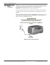
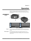
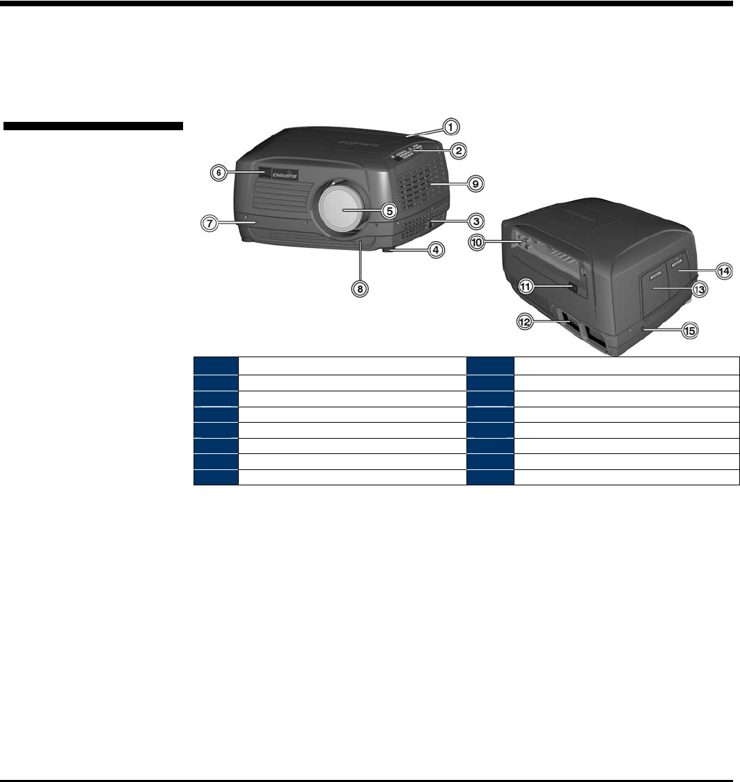
1 Top cover 9 Air vents
2 Built-in keypad 10 Rear input panel
3 AC receptacle 11 Rear IR sensor
4 Adjustable feet (3) 12 Rear exhaust
5 Projection lens 13 Lamp 1 Access (Door)
6 Front IR sensor 14 Lamp 2 Access (Door)
7 Bottom chassis 15 Slot for Kensington Security Lock
8 Lens release button
Figure 3.1. Projector Basics
(1) & (7) The projector’s top cover and bottom chassis form the shell of the projector.
All optical, electrical, and other miscellaneous components are housed between these
two parts.
(2) The built-in keypad is located on the top, right side of the projector. It’s an
alternate method to using the IR remote for projector control. It has a few less direct
keys than the IR remote, but includes an LED display, which continually displays the
projector’s status.
3.1 About the
Projector
Exterior f
Built-in Ke
yp
ad f


