


www.ti.com
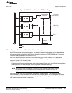
Peripheral Architecture
2.7.3 Possible Race Condition
A race condition may exist when certain masters write data to the DDR2 memory controller. For example,
if master A passes a software message via a buffer in DDR2 memory and does not wait for indication that
the write completes, when master B attempts to read the software message it may read stale data and
therefore receive an incorrect message. In order to confirm that a write from master A has landed before a
read from master B is performed, master A must wait for the write completion status from the DDR2
memory controller before indicating to master B that the data is ready to be read. If master A does not
wait for indication that a write is complete, it must perform the following workaround:
1. Perform the required write.
2. Perform a dummy write to the DDR2 memory controller module ID and revision register.
3. Perform a dummy read to the DDR2 memory controller module ID and revision register.
4. Indicate to master B that the data is ready to be read after completion of the read in step 3. The
completion of the read in step 3 ensures that the previous write was done.
For a list of the master peripherals that need this workaround, see the device-specific data manual.
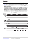
2.8 Refresh Scheduling
The DDR2 memory controller issues autorefresh (REFR) commands to DDR2 SDRAM devices at a rate
defined in the refresh rate (REFRESH_RATE) bit field in the SDRAM refresh control register (SDRFC). A
refresh interval counter is loaded with the value of the REFRESH_RATE bit field and decrements by 1
each cycle until it reaches zero. Once the interval counter reaches zero, it reloads with the value of the
REFRESH_RATE bit. Each time the interval counter expires, a refresh backlog counter increments by 1.
Conversely, each time the DDR2 memory controller performs a REFR command, the backlog counter
decrements by 1. This means the refresh backlog counter records the number of REFR commands the
DDR2 memory controller currently has outstanding.
The DDR2 memory controller issues REFR commands based on the level of urgency. The level of
urgency is defined in Table 7. Whenever the refresh level of urgency is reached, the DDR2 memory
controller issues a REFR command before servicing any new memory access requests. Following a REFR
command, the DDR2 memory controller waits T_RFC cycles, defined in the SDRAM timing 1 register
(SDTIM1), before rechecking the refresh urgency level.
In addition to the refresh counter previously mentioned, a separate backlog counter ensures the interval
between two REFR commands does not exceed 8× the refresh rate. This backlog counter increments by 1
each time the interval counter expires and resets to zero when the DDR2 memory controller issues a
REFR command. When this backlog counter is greater than 7, the DDR2 memory controller issues four
REFR commands before servicing any new memory requests.
The refresh counters do not operate when the DDR2 memory is in self-refresh mode.
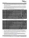
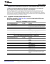
Table 7. Refresh Urgency Levels
Urgency Level Description
Refresh May Backlog count is greater than 0. Indicates there is a backlog of REFR commands, when the DDR2 memory
controller is not busy it will issue the REFR command.
Refresh Release Backlog count is greater than 3. Indicates the level at which enough REFR commands have been performed
and the DDR2 memory controller may service new memory access requests.
Refresh Need Backlog count is greater than 7. Indicates the DDR2 memory controller should raise the priority level of a
REFR command above servicing a new memory access.
Refresh Must Backlog count is greater than 11. Indicates the level at which the DDR2 memory controller should perform a
REFR command before servicing new memory access requests.
27
SPRU970G–December 2005–Revised June 2011 C6455/C6454 DDR2 Memory Controller
Submit Documentation Feedback
Copyright © 2005–2011, Texas Instruments Incorporated