


46
ICC
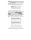
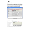
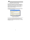
Figure 44: Alarm Configuration Box
“Enable” Check Box:
If checked, this alarm is active and will be evaluated
every second. If unchecked, this alarm is inactive and will therefore not be
evaluated.
Register:
Enter the drive register number that this alarm will continuously
monitor. For example, the alarm displayed in Figure 44 is configured to monitor
register 1302, which is “inverter status 1”.
Logical Comparison:
Choose a comparison operator which will be used to
compare the current value of the indicated “Register” with the reference
“Comparison Value”. Available selections are “less than” (<), “less than or
equal to” (<=), “greater than” (>), “greater than or equal to” (>=), “not equal to”
(!=), and “equal to” (=).
Comparison Value:
The reference comparison value is comprised of two
subcomponents: a “Mask” field and a “Value” field. Each time the alarm is
evaluated, the current value of the indicated “Register” is first bit-wise “AND”ed
with the “Mask” field. The resulting derived value is then compared with the
“Value” field by way of the “Logical Comparison” operator. While the “Mask”
field is always a hexadecimal number, the display and entry radix of the “Value”
field can be changed between decimal and hexadecimal with the associated
“DEC” and “HEX” buttons.
Registers that correspond to “analog” process variables (e.g. frequencies,
voltages, etc.) should typically have their “Mask” fields set to 0xFFFF, which
causes all data bits to be retained for the “Value” field comparison. For
registers that correspond to “enumerated” process variables (e.g. status words
where each bit of the register indicates a different item), however, the “Mask”
can be chosen to single out one or more specific data bits of the register. For
example, the “Mask” value of 0x1000 displayed in Figure 44 isolates bit #12 of
“inverter status 1”, which indicates whether or not the drive is in an emergency
stop condition. The “Value” field is also set to a hexadecimal value of 0x1000,
so the alarm condition will be evaluated as “true” when the emergency stop bit
equals 1.