


77
ICC
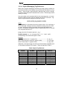
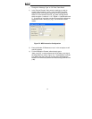
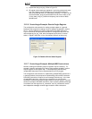
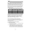
c) Expand the data_array tag. Refer to Figure 78.
d) 25 register values starting at register #11 are being continuously read
from the interface card and placed in the 25 sequential offsets of
data_array starting at the 11
th
offset (data_array[10]). In Figure 78, we
can see that data_array[10] (deceleration time #1) has a value of 100
(10.0s), data_array[11] (maximum frequency) has a value of 8000
(80.00Hz) etc.
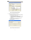
13.2.6 ControlLogix Example: Read a Single Register
The configuration and execution for reading a single register is in general
identical to that required for reading a block of registers as detailed in section
13.2.5. The only difference is in the configuration of the MSG instruction.
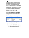
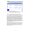
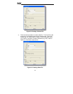
Figure 79 shows an example MSG instruction’s Configuration tab, which will
read a single tag (rd_reg_1402, which corresponds to the drive’s “inverter
status 1” register) and place it in the first element (offset 0) of data_array.
Figure 79: Read the Drive’s Status Register
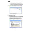
13.2.7 ControlLogix Example: Multiple MSG Instructions
At times, reading from different groups of registers may be necessary. For
example, a specific application may require some registers located in various
disjoint locations in the register map. To accomplish this task efficiently,
multiple MSG instructions can be implemented in the PLC program.
The configuration and execution for implementing multiple MSG instructions is
in general identical to that required for implementing just one MSG instruction.
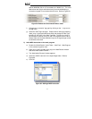
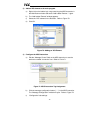
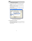
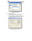
Each MSG instruction will require its own message controller tag. In the case
of read MSG instructions, more than one instruction may use the same
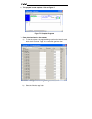
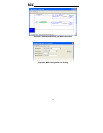
Destination Element tag, but the storage locations must not overlap. Figure 80
shows an example of two MSG instructions, each accessing different read tags.
It is evident from this logic that “rd_connection” and “rd_connection2” are the
two independent message controller tags created for these instructions.