


70
ICC
To read data from the interface card, the application PLC program must
reference a “source element” from which to start reading and the “number of
elements” to read. The “source element” will be a tag name constructed
according to the naming convention shown above, or a special tag as shown in
Table 3. The “source element” can be either a base tag (such as
“rd_reg_1301”, which starts at register 1301), or an offset from a base tag (such
as “rd_reg_1301[4]”, which starts at register 1301+4 = register 1305, the drive’s
input voltage monitor register).
In a similar manner, to write data to the interface card, the application PLC
program must reference a “destination element” to which to start writing and the
“number of elements” to write. Again, the “destination element” will be a tag
name constructed according to the naming convention shown above, or a
special tag as shown in Table 3.
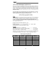
Whether reading or writing, the “number of elements” can be any quantity of
registers from 1 to the maximum allowable length (1485).
13.2.5 ControlLogix Example: Read a Register Block
This example program will show how to continuously read a block of registers
from the drive with a single MSG instruction. Only one read request is
outstanding at any given time.
1) Create new Tags.
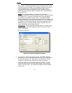
a) Double click “Controller Tags” in the controller organizer view.
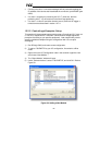
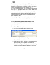
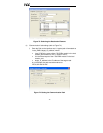
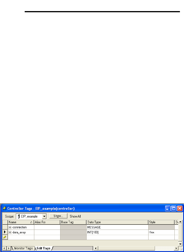
b) The “Controller Tags” window appears. Refer to Figure 67.
Figure 67: Create New Tags
c) Select the “Edit Tags” tab at the bottom.
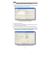
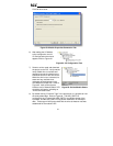
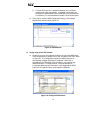
d) Create a new tag by entering “connection” in the first blank Name field,
and change its Data Type to “MESSAGE”. This tag will contain
configuration information for the MSG instruction.
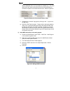
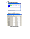
e) Select the “Monitor Tags” tab. Expand the “connection” tag by clicking
on the “+” sign next to the tag name. Scroll down to the
connection.UnconnectedTimeout field and change its value from the