


- 5 -
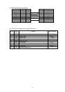
(14) RS-232 Interface pin configuration
Host Function 9 Pin 25 Pin 9 Pin Printer Function
1 +5V
RxD 2 3 2 TxD
TxD 3 2 3 RxD
DTR 4 20 4 DSR
GND 5 7 5 GND
DSR 6 6 6 RDY
RTS 7 4 7 N/C
CTS 8 5 8 RDY
9 +5V
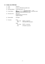
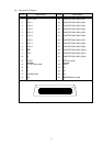
(15) Connector Pin Assignment and Signal Description
Pin No.
Signal
Name
Function Signal Direction
1 +5V Provide the power of 5V
2 TxD Transmit data Printer →
3 RxD Receive data ← Host
4 DSR Data set ready ← Host
5 GND General Ground
6 RDY Printer ready Printer →
7 N/C Not connected
8 RDY Printer ready Printer →
9 +5V Provide the power of 5V