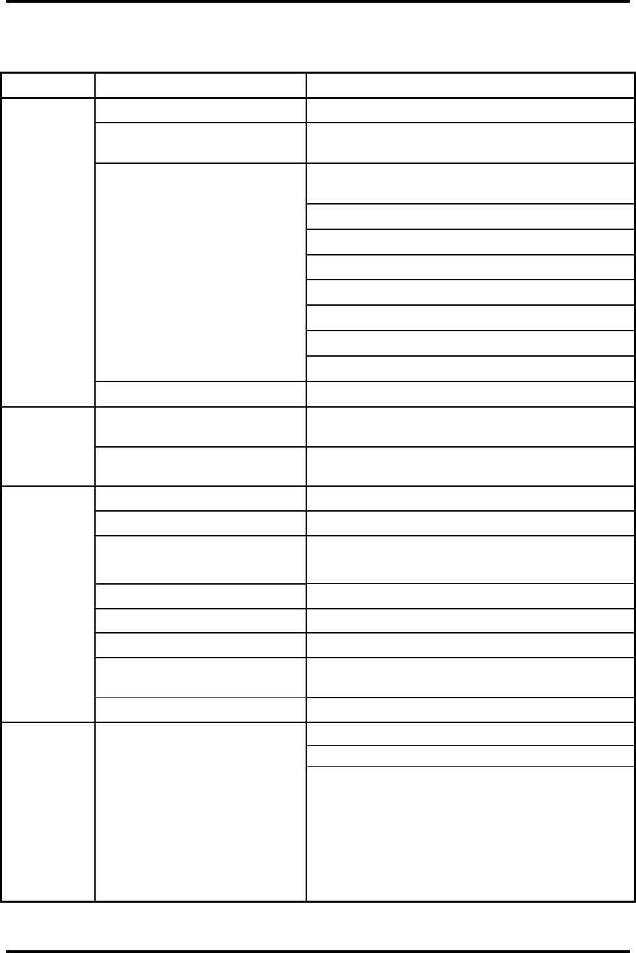
2.4 System Board Troubleshooting 2 Troubleshooting Procedures
TECRA M5 Maintenance Manual (960-542) [CONFIDENTIAL] 2-23
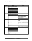
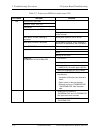
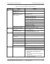
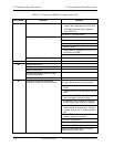
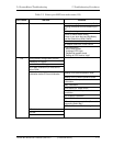
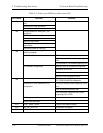
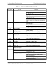
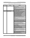
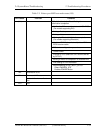
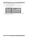
Table 2-5 Printer port LED boot mode status (3/9)
LED Status Test item Message
Prohibition of cache
Permission of L1/L2 cache in
FlashROM area
Initialization of H/W (before
DRAM recognition)
Initialization of MCH
Initialization of ICH.D30.Func0
Initialization of ICH.D31.Func0
Initialization of ICH.D31.Func1/2
Initialization of USB Controller
Initialization of ICH.D31.Func3
Initialization of ICH Audio
00h
Initialization of TI Controller
Initialization of PIT channel 1
(Setting the refresh interval to “30μs”)
Check of DRAM type and size
(at cold boot)
When unsupported memory is connected, becoming
HLT after beep sound
01h
SM-RAM stack area test HLT when DRAM size is 0
HLT When it can not be used as a stack
Cache configuration
Cache permission
CMOS access test
(at cold boot)
(HLT when an error is detected)
Battery level check of CMOS
CMOS checksum check
Initialization of CMOS data (1)
Setting of IRT status (Setting of boot status and IRT busy flag, The rest bits
are 0)
02h
Storing DRAM size in CMOS
Not resume when a CMOS error occurred
Not resume when resume status code is not set
Resume error check
S3 returning error (1CH) (Resume error LED=7AH)
SM-RAM checksum check (Resume error
LED=73H)
Check of memory configuration change (Resume
error LED=73H)
03h Resume branch (at cold boot)
RAM area checksum check in system BIOS
(Resume error LED=79H)


