4.11 Speaker/Fingerprint sensor board 4 Replacement Procedures
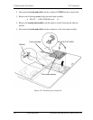
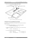
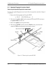
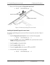
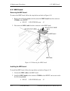
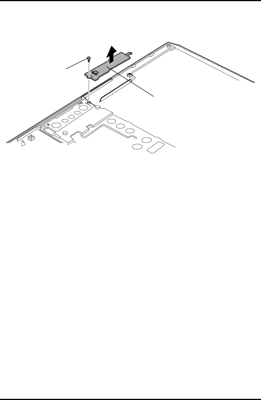
5. Remove the following screw and fingerprint sensor board.
• M2×3C S-FLAT HEAD screw x1
M2×3C S-FLAT HEAD
Fingerprint sensor board
Figure 4-18 Removing the fingerprint sensor board
Installing the Speaker/Fingerprint sensor board
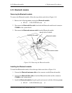
To install the speaker/fingerprint sensor board, follow the steps below and refer to Figure 4-
17 and 4-18.
1. Install the fingerprint sensor board and secure it with the following screw.
• M2×3C S-FLAT HEAD screw x1
2. Connect the SP FPC to the connector CN6170 on the system board and connector
CN950 on the fingerprint sensor board.
3. Install the speaker to the speaker holder.
4. Install the speaker holder to the slot.
5. Connect the speaker cable to the connector CN7 on the SP FPC.
6. Fix the SP FPC with the following screws.
• M2×3C S-FLAT HEAD screw x2
PORTEGE R200 Maintenance Manual (960-519) [CONFIDENTIAL] 4-29


