


2 Troubleshooting Procedures 2.12 Sound Troubleshooting
Procedure 2 Connector Check
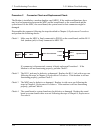
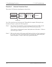
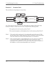
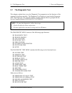
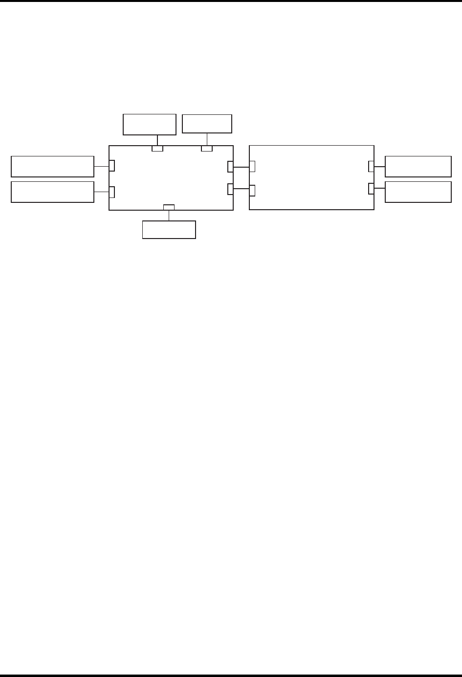
The sound function wiring diagram is shown below:
Sound board
PJ6000
PJ9600
PJ9601
MDC
Line In
PJ3010
External microphone
Headphone
PJ6004
PJ6001
System board
PJ9511
PJ9512
PJ9513
PJ9510
Speaker (Right)
Speaker (Left)
SD card
PJ2130
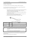
Any of the connections may be disconnected. Disassemble the computer following the steps
described in Chapter 4, Replacement Procedures and perform the following checks:
If the speakers don't work correctly, perform Check 1.
If the external microphone or the headphone doesn't work correctly, perform Check 2.
Check 1 If the speakers don't sound properly, the speaker cable may be disconnected. Make
sure the speaker cable is firmly connected to PJ9512 and PJ9513 on the system board.
If the stereo speakers are still not functioning properly, go to Procedure 3.
Check 2 If the external microphone or the headphone does not work correctly, the cable may
be disconnected. Make sure PJ9600 and PJ9601 on the sound board is firmly
connected to PJ9511 and PJ9510 on the system board. If the external microphone or
the headphone is still not functioning properly, go to Procedure 3.
2-56 Satellite A20 Maintenance Manual (960-444)