


4.30 Fluorescent Lamp 4 Replacement Procedures
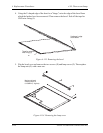
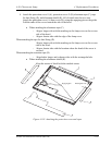
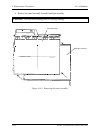
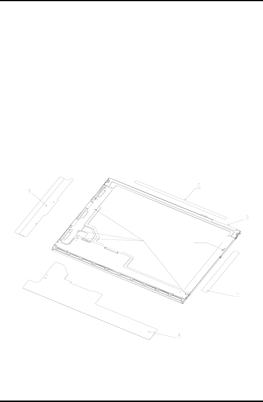
4. Attach the protection cover S (A), protection cover G (B), aluminum tape (C), tape
for lead fixing (D), and aluminum shield (K). All of which must be new ones.
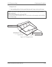
Attach the protection cover (A) then cover (B), using the engaging pins as the guide.
Fold the ends of the covers toward the side of the bezel.
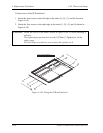
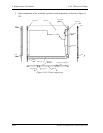
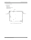
• When attaching the aluminum tape (C)
− Align a longer side with the marking on the lamp cover on the reverse
side of the bezel.
− Align a shorter side with the edge of the lamp cover.
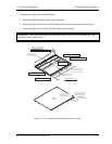
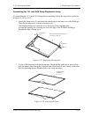
When attaching the tape for lead fixing (D)
Align a longer side with the marking on the lamp cover on the reverse
side of the bezel.
− Align a shorter side with the location where the head of the screw is
covered.
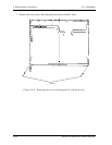
When attaching the retention tape (H)
− Align both a longer and a shorter sides with the rectangular hole.
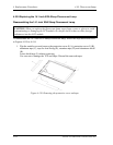
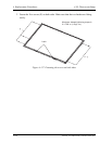
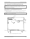
• When attaching the aluminum shield (K)
Align the corner of shield with the module corner.
Engaging pins
Rectangular hole
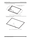
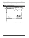
Figure 4-158 Attaching the protection cover and tapes
Satellite A20 Maintenance Manual (960-444) 4-197