


4.30 Fluorescent Lamp 4 Replacement Procedures
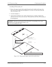
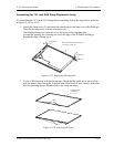
Attaching the tapes and insulation sheet
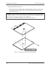
1. Attach the PCB insulation sheet (one location).
2. Attach the tape for the bezel to the bottom area close to the lamp (two locations).
3. Attach the tape for fixing the FL tube cable (one location).
CAUTION: When attaching tape and insulation sheet, use care not to damage the TAB
and lamp cable connections.
≃V[ ƒg‚ Ì‚ ½‚ í‚ Ý–³‚ «‚ 悤“\ ‚ è t ‚ ¯‚ éD
2
1
æ ‚ èã ‚˚ ‚Ä –³‚¢ ‚± ‚Æ
‚o ‚b ‚a ‚ª ƒt ƒŒ[ƒ ‚É
‰Ÿ‚µ ‚È ‚ª ‚ç “\ ‚é D
ƒxƒ[ƒ‹‚ª ‚‚© ‚È‚¢—lC
ƒxƒ[ ƒ‹ƒe[ ƒv“\‚ è t ‚ ¯
≃V[ ƒg“ \ ‚ è t‚ ¯
1
ƒŠƒt ƒŒƒNƒ^’[ ‚ð –ÚˆÀ‚É“\ ‚é
ƒ‚ ƒWƒ…[ ƒ‹ ’ [‚ ð–ÚˆÀ‚ É“ \‚ é
ƒ‚ ƒWƒ…[ ƒ‹’ [‚ ð–ÚˆÀ‚ É“ \ ‚ é
ƒ‚ ƒWƒ…[ ƒ‹ \–Ê‚ Éo ‚È‚¢ ‚± ‚Æ
ƒ‚ ƒWƒ…[ ƒ‹ \–Ê‚ Éo ‚È‚¢ ‚± ‚Æ
ƒŠƒt ƒŒƒNƒ^’[ ‚ð –ÚˆÀ‚É“\ ‚é
2
5
ƒP[ ƒuƒ‹ ˆø‚ «o ‚µ Œû‚𠢂¤‚± ‚Æ
ƒSƒ ƒLƒƒƒbƒvF
ƒ‚ ƒWƒ…[ ƒ‹’ [‚ ð–ÚˆÀ‚É“\‚ é
“\ ‚èŠî F
ƒxƒ[ƒ‹ ’[ ‚© ‚ço ‚È‚ ¢‚±‚ Æ
“\ ‚èŠî F
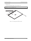
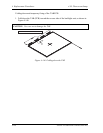
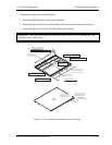
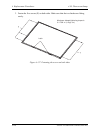
Attaching the insulation sheet
Attach the sheet after removing slack.
The frame must not be
overlaid with the PCB.
Align the sheet with the module's edge.
Ali
g
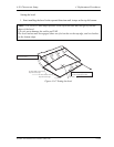
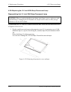
n the sheet with the reflector's ed
g
e.
Align the sheet with the reflector's edge.
Align the sheet with the module's edge.
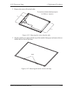
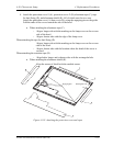
The tape edge must not protrude
from the surface of the module.
The tape edge must not protrude
from the surface of the module.
Attach the sheet by
pressing it so that the
bezel may not "fly".
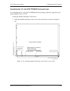
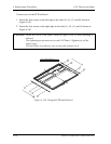
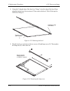
Attaching the tape for the bezel
Requirements for attachment:
The tape edge must not go
beyond the bezel's edge.
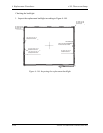
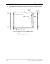
Requirements for attachment:
The tape edge must not go
beyond the module's edge.
Rubber cap:
Must cover the
opening for the cable.
Figure 4-149 Attaching the insulation sheet and tape
Satellite A20 Maintenance Manual (960-444) 4-191