


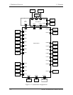
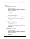

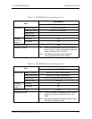
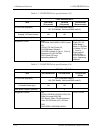

1 Hardware Overview 1.2 System Unit Block Diagram
KBC/EC (Keyboard Controller/Embedded Controller)
• One M306K9FCLRP chip functions as both KBC and EC.
• KBC has the following functions:
– Scan controller to check status of keyboard matrix
– Interface controller between the keyboard scan controller and the system
• EC has the following functions:
– Power supply sequence control
– System I/F
– Thermal conditions control
– Flash rewriting
PSC (Power Supply Controller)
• One TMP87PM48V chip is used.
• This controller controls the power sources.
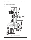
Onboard memory: 0MB
Optional memory
Two SO-DIMM slots are available for 128, 256, 512MB and 1GB memory modules,
consisting of SDRAM chips.
• PC2100
• 3.3 volts operation
• No parity bit
• Data transfer width is 64-bit
• 128/256/512/1024 MB selectable
– 128MB: eight 128Mbit (8M x 16bit) chips
– 128MB: four 256Mbit (16M x 16bit) chips
– 256MB: eight 256Mbit (16M x 16bit) chips
– 512MB: eight 512Mbit (32M x 16bit) chips
– 1GB: eight 1Gbit (64M x 16bit) chips
Sound CODEC
• One AD1981B chip is used.
• Internal Audio Controller is integrated into the MM1535+ chip.
Both chips are used as the CODEC chip.
Battery E
2
PROM: ST24C04FM
• One ST24C04FM equivalent (128 words × 16-bit, I
2
C-Interface) is used.
This memory maintains records of battery use.
1-12 Satellite A20 Maintenance Manual (960-444)