


4.30 Fluorescent Lamp 4 Replacement Procedures
Assembling PCB-assembly cell
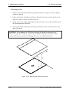
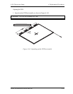
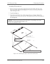
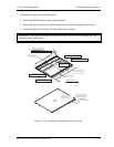
1. Remove the paper (coated with a mold release) from the double-sided tape in the
three areas on the replacement backlight unit. The areas are at the top and on both
sides. See Figure 4-145.
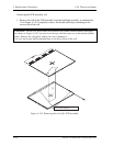
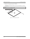
2. Turn the backlight on.
3. Check that the backlight is free of dust, foreign objects, or damage. Perform this
check also for the reverse side of the cell. Then install the cell of the PCB assembly in
the backlight unit.
CAUTION: Align the top left corner of the cell with the corresponding corner of the
backlight unit, as indicated by
②
in Figure 4-145.
Use care not to damage the TAB.
2
1
—¼–ʃe[ ƒv ” —£ †‚Æ‚é F ‚ R‰ÓŠ
¶ ã “ Ë‚«“–‚Ä
‚o‚b‚a t‚« ƒZƒ‹
ƒoƒbƒNƒ‰ƒCƒg
Cell of PCB
Backlight
Align the top left
corner.
Remove the paper on the double-side tape (three locations).
Figure 4-145 Removing the paper coated with a mold release
Satellite A20 Maintenance Manual (960-444) 4-187