


COURIER HIGH SPEED MODEMS
Internal Modem Set Up 3-5
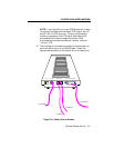
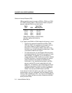
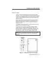
Reset the Jumpers
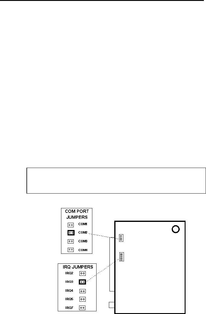
Figure 3.1 shows an enlarged view of the modem's jumper
switches. If you hold the modem so that the rear panel is at the
bottom and the edge connector is at the left of the circuit board
you can locate the COM and IRQ jumpers near the center left
side of the board.
Each jumper has two upright contacts connected by a black
plastic piece, called a shunt, placed over the contacts for the
COM2 and IRQ3 settings. This shunt selects the jumper by
closing the circuit.
To change a jumper setting, gently lift off the black shunt and
replace it over the contacts you want.
As we've said, your choice of an IRQ for COM3 or COM4
depends on your hardware/software configuration. If the
device at COM1 or COM2 isn't using IRQ4 or IRQ3, you may
use one of them. Otherwise, check your PC and software
documentation to see if you may use IRQ2, IRQ5 or IRQ7.
WARNING: Do not select an IRQ position until you've read
the previous guidelines and reviewed your software docu-
mentation.
Figure 3.1Jumper Switch/Serial Port Settings