Watlow EZ-ZONE
®
PM Integrated Controller • 26 • Chapter 4 Home Page
Chapter 4: Home Page
4
Custom Menu
Number
Home
Page
Display
(defaults)
Parameter Name Settings Custom
Menu
Display
(defaults)
Parameter Page and Menu
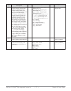
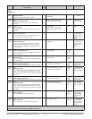
1 Upper Display (value only) Active Process Value
[Ac;Pu]
Operations Page, Analog Iput Menu
2 Lower Display (value only) Active Set Point
[Ac;SP]
Operations Page, Profile Status Menu
3
[C;;M1]
Control Mode
[`C;M]
Operations Page, Loop Menu
4
[h;Pr1]
Heat Power
[`h;Pr]
Operations Page, Monitor Menu
5
[C;Pr1]
Cool Power
[`C;Pr]
Operations Page, Monitor Menu
6
[AUt1]
Autotune
[`AUt]
Operations Page, Loop Menu
7
[id;S1]
Idle Set Point
[idLE]
Operations Page, Loop Menu
8
[P;;St1]
Profile Start
[P;Str]
Home Page only (See Profile Page Chapter.)
9
[P;;AC1]
Profile Action Request
[P;ACr]
Home Page only (See Profile Page Chapter.)
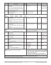
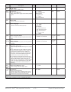
10 to 20 (skipped) None
[nonE]
(Add parameters to the Home Page in the Custom
Menu, Factory Page.)
Default Home Page
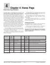
The Home Page is a customized list of as many as 20
parameters that can be configured and changed in
the Custom Menu [ CUSt] (Factory Page). The default
list of nine parameters below includes the Active
Process Value (value in upper display) and Active Set
Point (value in lower display). The Attention [Attn]
parameter appears only if there is an active message.
An active message could be a reported error, for ex-
ample, [C;Er1] (Current Error), or it could be for in-
formation only, for example, [tUN1] (Autotuning).
Use the Advance Key ‰ to step through the other
parameters. The parameter prompt will appear in
the lower display, and the parameter value will ap-
pear in the upper display. You can use the Up ¿ and
Down ¯ keys to change the value of read-write pa-
rameters, just as you would in any other menu.
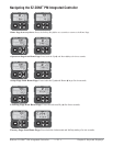
If Control Mode is set to Auto, the process value
is in the upper display and the Closed Loop Set Point
(read-write) is in the lower display.
If a profile is running, the process value is in the
upper display and the Target Set Point (read only) is
in the lower display.
If Control Mode is set to Manual, the process val-
ue is in the upper display and the output power level
(read-write) is in the lower display.
If Control Mode is set to Off, the process value is
in the upper display and [`oFF] (read only) is in the
lower display.
If a sensor failure has occurred, [----] is in the
upper display and the output power level (read-write)
is in the lower display.
Changing the Set Point
You can change the set point by using the Up ¿ and
Down ¯ keys, when a profile is not running.
If the set point is displayed and the % indicator is
lit, the controller is in open-loop (manual) mode.
Note: Avoid continuous writes within loops. Excessive writes to
EEPROM will cause premature EEPROM failure. The EEPROM is
rated for 1,000,000 writes.
Default Home Page Parameters


