Watlow EZ-ZONE
®
PM Integrated Controller • 67 • Appendix
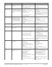
Indication Description Possible Cause(s) Corrective Action
[Li;h1] Limit High
[Li;h2]
Sensor input above high limit
set point
• Temperature is greater than limit set
point
• Limit outputs latch and require reset
• Incorrect alarm set point
• Check cause of over temperature
• Clear limit
• Establish correct limit set point
[LP;o1]
Loop Open Error
Open Loop Detect is active
and the process value did
not deviate by a user-select-
ed value in a user specified
period.
• Setting of Open Loop Detect Time
incorrect
• Setting of Open Loop Detect Devia-
tion incorrect
• Thermal loop is open
• Open Loop Detect function not re-
quired but activated
• Set correct Open Loop Detect Time for
application
• Set correct Open Loop Deviation value
for application
• Determine cause of open thermal loop:
misplaced sensors, load failure, loss of
power to load, etc.
• Deactivate Open Loop Detect feature
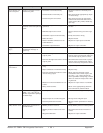
[LP;r1]
Loop Reversed Error
Open Loop Detect is active
and the process value is
headed in the wrong direc-
tion when the output is
activated based on devia-
tion value and user-selected
value.
• Setting of Open Loop Detect Time
incorrect
• Setting of Open Loop Detect Devia-
tion incorrect
• Output programmed for incorrect
function
• Thermocouple sensor wired in reverse
polarity
• Set correct Open Loop Detect Time for
application
• Set correct Open Loop Deviation value
for application
• Set output function correctly
• Wire thermocouple correctly, (red wire
is negative)
[`rP1] Ramping 1
Controller is ramping to new
set point
• Ramping feature is activated • Disable ramping feature if not re-
quired
[tUN1] Autotuning 1
Controller is autotuning the
control loop
• User started the autotune function
• Digital input is set to start autotune
• Wait until autotune completes or dis-
able autotune feature
• Set digital input to function other
than autotune, if desired
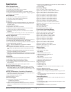
No heat/cool action Output does not activate load • Output function is incorrectly set
• Control mode is incorrectly set
• Output is incorrectly wired
• Load, power or fuse is open
• Control set point is incorrect
• Incorrect controller model for applica-
tion
• Set output function correctly
• Set control mode appropriately (Open
vs Closed Loop)
• Correct output wiring
• Correct fault in system
• Set control set point in appropriate
control mode and check source of set
point: remote, idle, profile, closed loop,
open loop
• Obtain correct controller model for ap-
plication
No Display No display indication or LED
illumination
• Power to controller is off
• Fuse open
• Breaker tripped
• Safety interlock switch open
• Separate system limit control acti-
vated
• Wiring error
• Incorrect voltage to controller
• Turn on power
• Replace fuse
• Reset breaker
• Close interlock switch
• Reset limit
• Correct wiring issue
• Apply correct voltage, check part
number
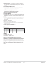
No Serial Communi-
cation
Cannot establish serial com-
munications with the con-
troller
• Address parameter incorrect
• Incorrect protocol selected
• Baud rate incorrect
• Parity incorrect
• Wiring error
• EIA-485 converter issue
• Incorrect computer or PLC communi-
cations port
• Incorrect software setup
• Termination resistor may be required
• Set unique addresses on network
• Match protocol between devices
• Match baud rate between devices
• Match parity between devices
• Correct wiring issue
• Check settings or replace converter
• Set correct communication port
• Correct software setup to match con-
troller
• Place 120 Ω resistor across EIA-485
on last controller


