


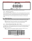
4.2.2. DC Powered Units
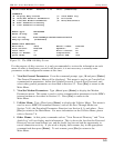
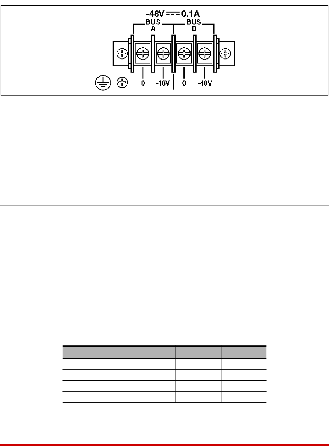
When connecting the SRM to a -48 VDC power source, first remove the protective cover from
the DC terminal block. Switch off the DC power source, then attach the wires from the power
source to the screw terminals, and connect your ground line to the labeled ground screw. Next,
replace the protective cover, and switch the DC power source back on. Note that the DC
terminal block features a dual bus configuration to allow connection to a back-up power
supply.
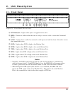
4.3. SetUp Switches
The SetUp Switches select default settings for Modem Port baud rate, flow control, parity,
rings to answer, ARQ/Compression, the modem speaker, and the SRM-100 Security Mode.
Note: Operating values for these parameters can also be selected via the SRM’s
configuration menus. However, if the unit is reset to default parameters, these
settings will return to the default values selected by the SetUp switches.
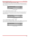
4.3.1. Default Modem Baud Rate (Sw1, Sw2)
SetUp Switches one and two select the default baud rate for the SRM’s internal modem and the
serial Modem Port. The Modem Baud Rate can also be selected via the Modem Parameters
Menu (/M). If the unit is reinitialized, the baud rate will return to the setting specified by
SetUp Switches one and two.
Note: Automatic baud rate sensing is disabled. This allows the SRM to function
with devices that do not automatically negotiate the baud rate.
Default Modem Baud Rate Sw1 Sw2
9600 bps * Down Down
38.4K bps Down Up
19.2K bps Up Down
2400 bps Up Up
* = Factory Setting
4-2
SRM-100 - Secure Rack Modem, User's Guide Hardware Installation
Figure 4.1: Terminal Block Assembly and Grounding Screw (DC Units Only)