


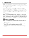
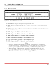
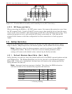
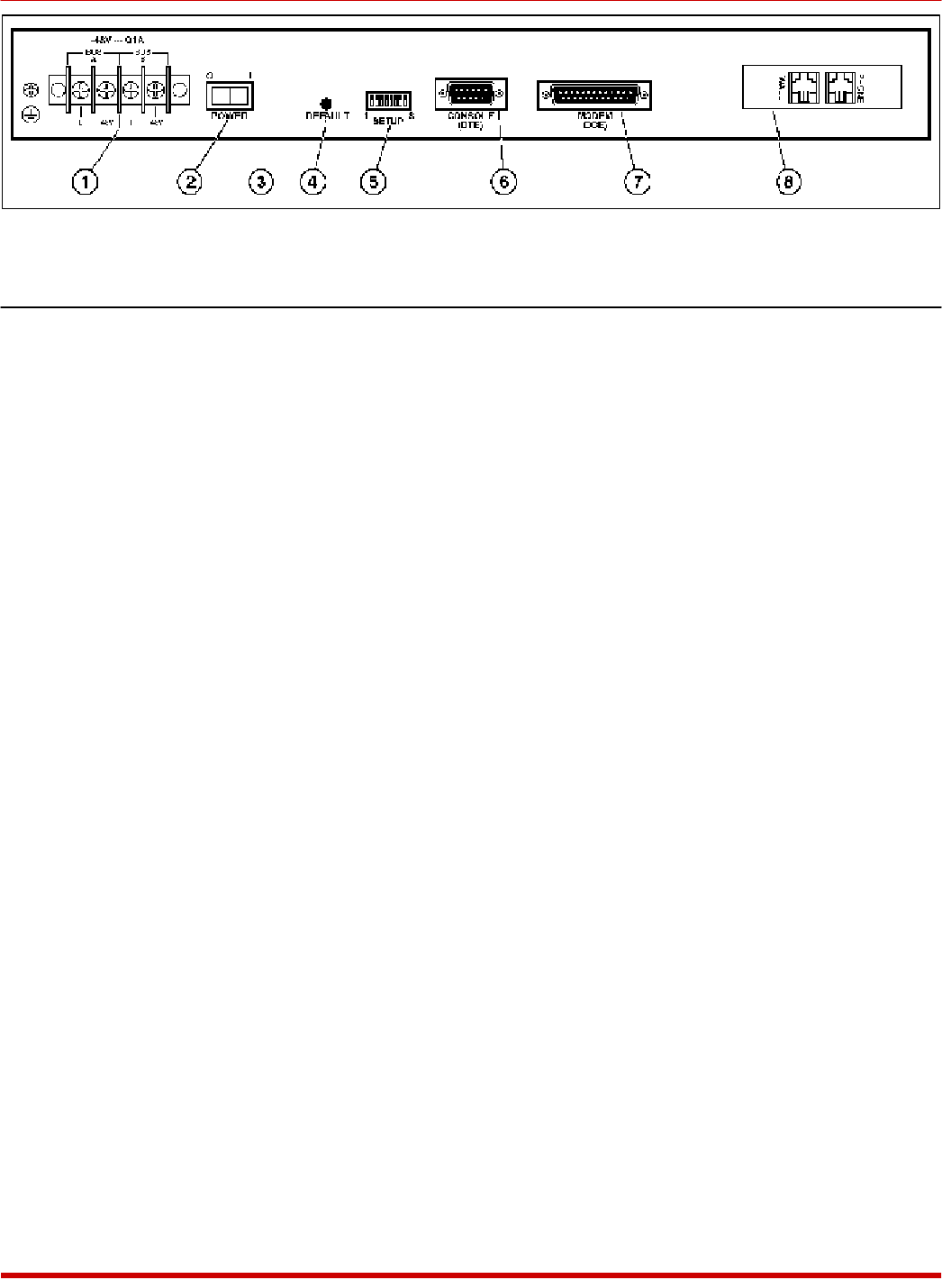
2.2. Back Panel
À
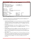
Power Input: (DC Unit Shown) The DC version includes a dual-bus terminal block for
-48 VDC operation and a ground screw. The AC version includes an IEC-32 inlet for
connection to a three wire (grounded) power cord (supplied with unit).
Á
Power Switch
Â
Voltage Selector Switch: (AC Units Only) For selecting 115 VAC or 230 VAC
operation .
Ã
Default Button: Resets unit to default parameters and erases the Password Directory as
described in Section 4.4.
Note: The default procedure will clear all menu-selected parameters, and erase the
Password Directory.
Ä
SetUp Switches: Eight DIP switches, which select the default Modem Baud Rate,
Flow Control, Parity, Rings to Answer, Compression, Speaker (On/Off) and Security
Mode. For more information on the SetUp Switches, refer to Section 4.3.
Å
Console Port: For connection to your PC, terminal, or other device. Allows access to
Command Mode. DB9, RS232, DTE configuration. Note that the command mode can
also be accessed via modem as explained in Section 5.1.2.. Appendix A.1 describes the
Console Port interface.
Æ
Modem Port: For connection to the secure device. The SRM-100 will protect dial-up
access to this device by requiring a password and/or calling the user back at a predefined
number. Appendix A.2 describes the Modem Port interface.
Ç
Telco Line: For connection to your telecommunications (telephone) line. The RJ11 Jack
labeled "Wall" or "Line" is used for connection to your telco line. The Jack labeled
"Phone" is not used.
2
SRM-100 - Secure Rack Modem, User's Guide Table of Contents
Figure 2.2: Back Panel (DC Version Shown)