


Release 1.1 xv
List of Figures
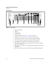
Figure 1.1 Front Panel . . . . . . . . . . . . . . . . . . . . . . . . . . . . . . . . . . . . . . . . . . . . .18
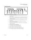
Figure 1.2 Front Panel Display, Status Annunciators. . . . . . . . . . . . . . . . . . . . . .19
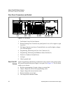
Figure 1.3 Rear panel. . . . . . . . . . . . . . . . . . . . . . . . . . . . . . . . . . . . . . . . . . . . . .20
Figure 1.4 Programming and Monitoring S1 Switch . . . . . . . . . . . . . . . . . . . . . . .21
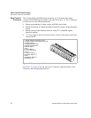
Figure 1.5 Programming and Monitoring J1 Connector . . . . . . . . . . . . . . . . . . . .22
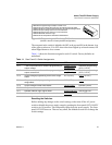
Figure 2.1 Shipping or Storage Carton Label . . . . . . . . . . . . . . . . . . . . . . . . . . . . 28
Figure 2.2 Unpacking the Power Supply. . . . . . . . . . . . . . . . . . . . . . . . . . . . . . . .30
Figure 2.3 Mounting the Power Supply in the Rack With Support Rails. . . . . . . .31
Figure 2.4 AC Input Connector . . . . . . . . . . . . . . . . . . . . . . . . . . . . . . . . . . . . . . .32
Figure 2.5 Attaching the AC Input Wires. . . . . . . . . . . . . . . . . . . . . . . . . . . . . . . .34
Figure 2.6 Fastening the Output Wires. . . . . . . . . . . . . . . . . . . . . . . . . . . . . . . . .43
Figure 2.7 Output Bus Bar Cover . . . . . . . . . . . . . . . . . . . . . . . . . . . . . . . . . . . . .44
Figure 2.8 Output Cover with Strain Relief . . . . . . . . . . . . . . . . . . . . . . . . . . . . . . 44
Figure 4.1 Location of J1 and S1 . . . . . . . . . . . . . . . . . . . . . . . . . . . . . . . . . . . . .60
Figure A.1 Power Supply Dimensions. . . . . . . . . . . . . . . . . . . . . . . . . . . . . . . . . .76