


About The XPR Power Supply
Rear Panel Connectors and Switch
20 Operating Manual for XPR Series Power Supply
Rear Panel Connectors and Switch
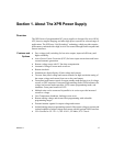
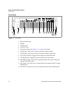
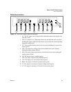
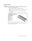
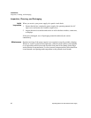
Figure 1.3 Rear panel
1. Fan Exhaust Vents: Do Not Obstruct.
2. Remote Sensing Ports: From the rear panel point of view, left is negative; right
is positive.
3. DC Output: Bus bars are shown. Terminal blocks are used for higher voltages
(150 Vdc and higher).
4. Programming, Monitoring and User Line Connector (J1).
5. Programming, Monitoring and Shutdown Select Switch (S1).
6. Protective Conductor Ground Screw.
7. Ac Input.
8. Chassis ground stud.
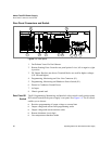
Rear Panel S1
Switch
The S1 Programming, Monitoring, and Interlock select switch is an 8-position piano
DIP switch located on the power supply’s rear panel. See Figure 1.4. The S1 switch
enables you to choose:
• Resistive programming of output voltage or current limit
• Output voltage and current limit programming scales
• Output voltage and current monitor scales
• Remote shutdown circuit logic
• Over temperature shutdown mode
1 3
8 6 7
1 1
2
4
5