


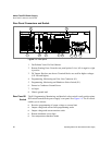

About The XPR Power Supply
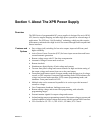
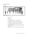
Rear Panel Connectors and Switch
Release 1.1 23
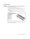
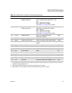
Table 1.2 Rear Panel J1 Connector Terminals and Functions
Pin Reference Name Function In/Output
J1-1 VPGM Output Voltage
Programming Input
Input for voltage programming signals
from a voltage source (select S1-5 = ON
and:
S1-3 = OFF for 0-5 V range
S1-3 = ON for 0-10 V range
(see Table 4.3, on page 63 for details)
Input
J1-2 IPGM Output Current Limit
Programming Input
Input for current limit programming
signals from a voltage source (select
S1-6 = ON and:
S1-4 = OFF for 0-5 V range
S1-4 = ON for 0-10 V range
(see Table 4.3, on page 63 for details)
Input
J1-3 RTN-P
1
1. Both RTN-PGM and RTN-MON are connected at the same potential.
Program Return Return for voltage and current
programming signals
Input
J1-4 VMON Output Voltage Monitor Output for output voltage monitor signal Output
J1-5 IMON Output Current Monitor Output for output current monitor signal Output
J1-6 RTN-M
1
Monitor Return Return for voltage and current monitoring
signals
Output
J1-7 N/C No connection None. N/C
J1-8 GND-U
2
2. An isolated (see footnote below) supply voltage is available for external usage (e.g. remote on/off line). Its internal
impedance is approximately 100 Ω.
Return of 15 V User Signal Return for 15 V isolated
3
supply voltage.
3. User supply is isolated to 600 V from the power supply output and chassis.
Output
J1-9 +15V-U + 15 V User Signal + 15 V isolated voltage supply Output
J1-10 N/C No connection None. N/C
J1-11 RTN-I
4
4. Safety Interlock circuit is isolated to 600 V from the power supply output and chassis.
Return Interlock Return safety interlock (shutdown) Input
J1-12 INT Interlock Signal (4-15 V) Safety interlock (shutdown) 4-15 V Input
J1-13 N/C No connection None. N/C
J1-14 RTN Return Shutdown Return master/slave S/D signal Input
J1-15 S/D Shutdown Shutdown master/slave signal (5-15 V) Input